4 Wire Rtd Wiring Diagram

Simple Realization Of A Fully Integrated 4 Wire Rtd Temperature Measurement System For High Precision Measurement Applications Analog Devices
Rtd S 2 3 Or 4 Wires Connection Tekon Electronics
How To Hook Up A 4 Wire Pt100 And How To Get Temperature From It
2 3 4 Wire Rtd Circuit Circuitlab

Cn0381 Circuit Note Analog Devices
Resolved Ads1148 Circuit Design For 2 3 Or 4 Wire Rtd Or Thermocouple Input Data Converters Forum Data Converters Ti E2e Support Forums
Wiring diagrams help technicians to find out the way the controls are wired to the system.
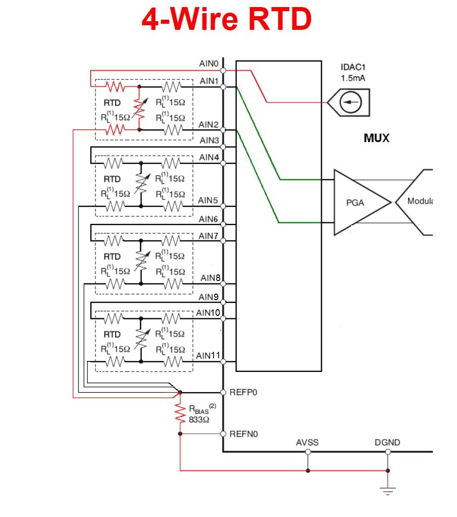
4 wire rtd wiring diagram. A common version is the constant current circuit shown here. 4 wire rtd principle. 4 wire rtd wiring diagram. Normally a 2 wire rtd will lose accuracy due to the resistance in the cable which can be thousands.
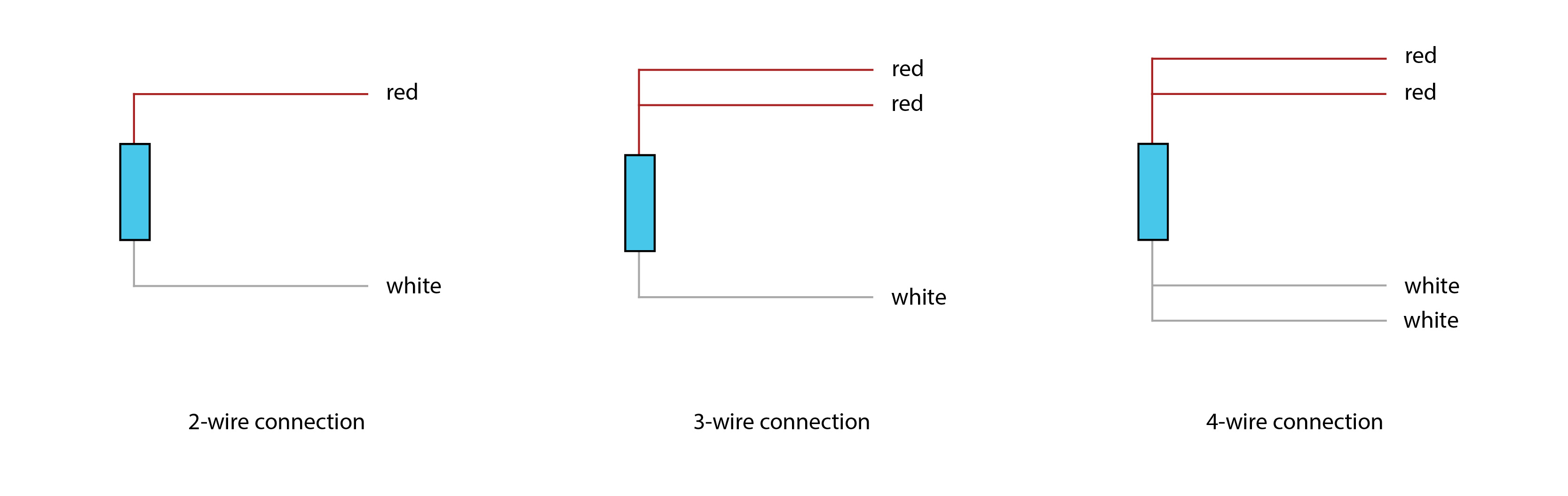
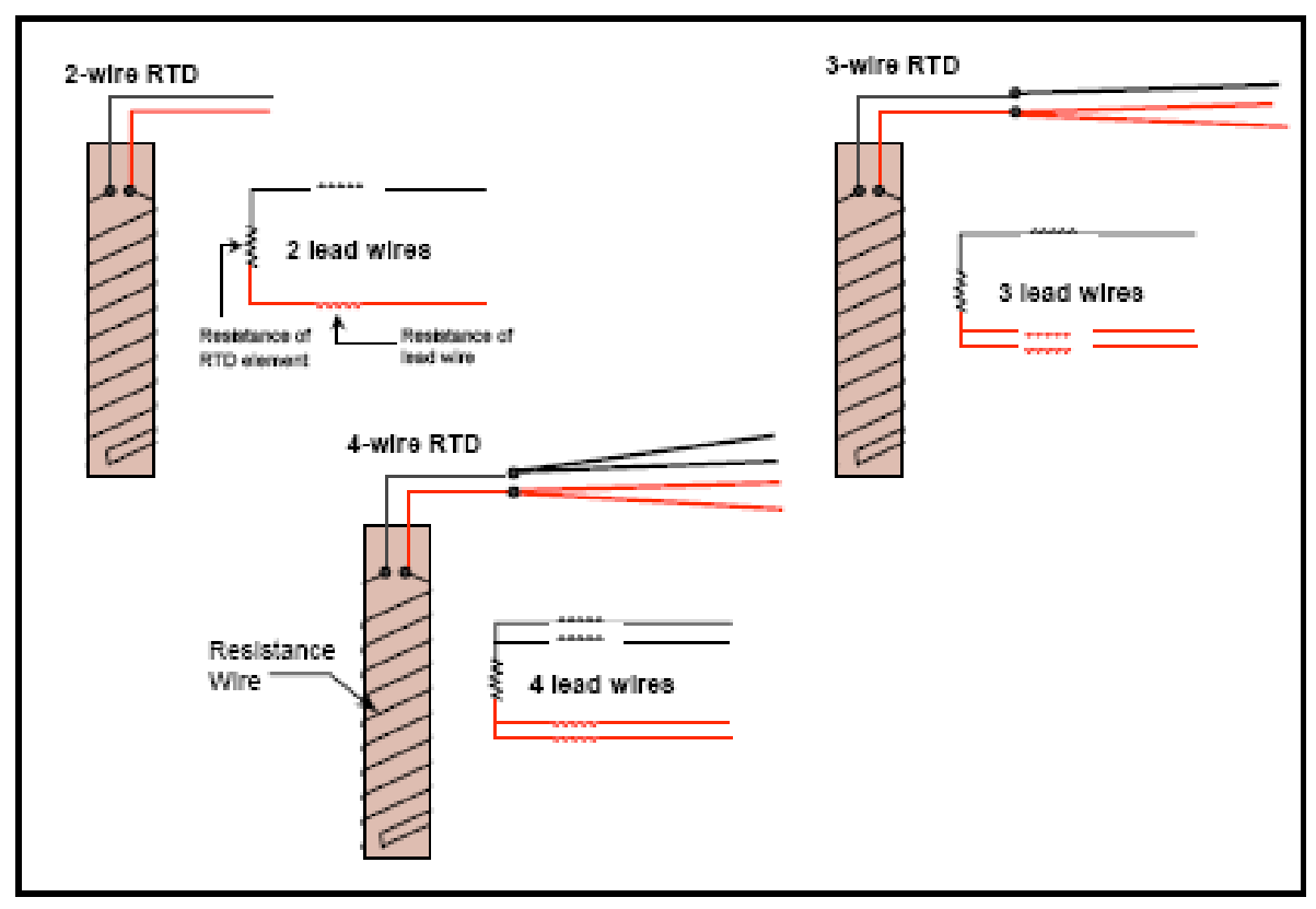
Connect the black or white lead on the negative side for the resistive element to the excitation and channel negative on the daq device. Connect each of the red leads on the positive side of the resistive element to the excitation positive and channel positive on the daq device. 4 wire rtd signal connection. L2 and l3 measure the voltage drop across the rtd element.
4 wire construction is used primarily where close accuracy is required. A wiring diagram is a streamlined conventional photographic representation of an electric circuit. 4 wire rtd wiring diagram. Please download these 4 wire rtd wiring diagram by using the download button or right click selected image then use save image menu.
A wiring diagram is a streamlined conventional pictorial depiction of an electric circuit. 4 wire rtd circuits not only cancel lead wires but remove the effects of mismatched resistances such as contact points. Variety of 4 wire rtd wiring diagram you can download totally free. Variety of 4 wire rtd wiring diagram.
The most accurate lead wire configuration is the true 4 wire configuration. Collection of 4 wire rtd wiring diagram. A 2 wire configuration with a compensating loop is also an option. L1 and l3 carry the measuring current while l2 acts only as a potential lead.
It shows the elements of the circuit as simplified forms and also the power and also signal links between the devices. In this circuit there are three leads coming from the rtd instead of two. Is drives a precise measuring current through l1 and l4. No current flows through it while the bridge is in balance since l1 and l3 are in separate arms of the bridge resistance is canceled.
It reveals the components of the circuit as streamlined shapes and the power and also signal connections between the devices. However many people using and specifying rtd s do not realize that 2 wire 3 wire and 4 wire rtd sensors can be used interchangeably with very little difference in accuracy.
Http Www Jms Se Com Catalog Rtd Wire Pdf

Oil And Gas Engineering 2 Wires 3 Wires Or 4 Wires Rtd Resistance Temperature Detector

Diagram Trailer Wiring Diagram 4 Wire Full Version Hd Quality 4 Wire Cb640wiringpdf Liceoclassicoforli It

Diagram Gibson P100 Wiring Diagram Full Version Hd Quality Wiring Diagram Flowdiagram Vagalume Fr

Diagram Three Wire Rtd Wiring Diagram For Full Version Hd Quality Diagram For Aerodatabase Creapitchoune Fr
Diagram 4 Wire Inte Wiring Diagram Full Version Hd Quality Wiring Diagram Mami Diagram Radd Fr
Explain Rtd Construction And Types Of Rtd Paktechpoint

Km 9460 Wire Pt100 Free Download Wiring Diagrams Pictures Wiring Schematic Wiring

Nf 4218 Further 3 Wire Rtd Wiring Diagram Also Hdmi Cable Wiring Diagram Free Diagram

Crocsee Rtd Pt100 Temperature Sensor Probe 3 Wires 2m Cable Thermocouple 58 572 F 50 300 C 1 2 Npt Thread Amazon Com Industrial Scientific
Wrg 0704 2wire Rtd Diagram

Bl 9269 Wire Pt100 Free Download Wiring Diagrams Pictures Wiring Download Diagram
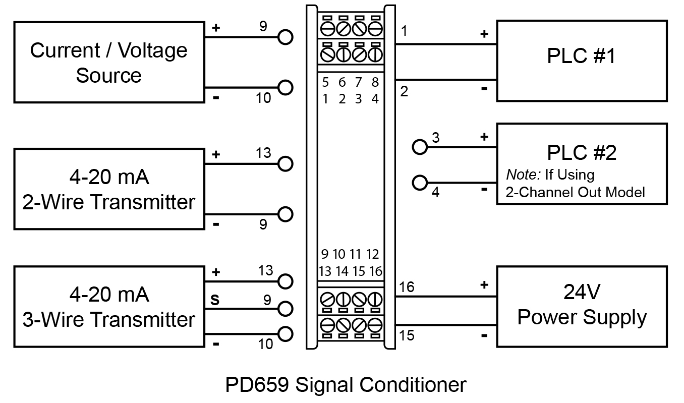
Diagram In Pictures Database Fluke 744 3 Wire Rtd Diagram Just Download Or Read Rtd Diagram Eric Berger Bi Wiring Speakers Onyxum Com
