5 Wire Rc Servo Wiring Diagram
How To Controll A Servo With 5 Wires

Peredelka Servy Wltoys S 5 Pin Na 3 Pin Ppm Youtube

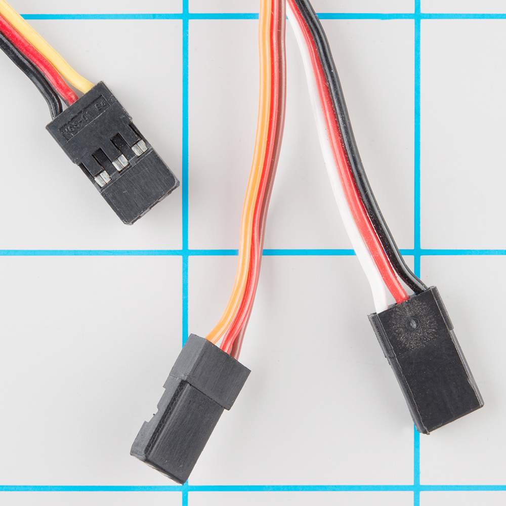
Rc Quick Tip Understanding The Servo Wire Colours Youtube
Hobby Servo Tutorial Learn Sparkfun Com
.jpg)
Diagram Rc Model Boat Wiring Diagram Full Version Hd Quality Wiring Diagram Cheyennebitwaredownload Rapfrance Fr
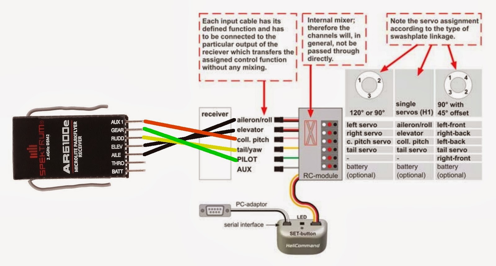
Diagram Servo For Rc Helicopter Wiring Diagram Full Version Hd Quality Wiring Diagram Diagrame Ebizmed Fr
For futaba hitec and jr radio the servo and battery connections have the right polarity and signal wires although the connectors are physically different.
5 wire rc servo wiring diagram. Except at the switch in this case both motor legs rest at ground. A wiring diagram is a simplified conventional pictorial depiction of an electric circuit. How to make a simple remote controlled plane custom maker pro wiring the control system for an electric powered rc airplane diagram servo wire full version hd quality wikidiagrams siggy2000 de ro 5844 blue arrow pp 10b aircraft electronic sd embedded ammeter mb 6115 car diagrams 3 channel coronadelvista datajob2018 fr add seperate power supply retract by gibbs read more. You can mix futaba servos with an airtronics receiver mix hitec jr servos with a futaba receiver etc.
Power ground and signal. You can mix futaba servos with an airtronics receiver mix hitec jr servos with a futaba receiver etc. As long as you are careful about polarity. Somewhere along the line the wiring didn t become compatible.
Variety of servo motor wiring diagram. Wiring a servo motor is very easy because you only need to connect three wires. The switch when moved in either direction applies both power and ground directly to motor legs without the use of any relays. In futaba hitec and jr radio servos the servo and battery connections have the same polarity and signal wiring although the connectors are slightly different.
The power wire is typically red and needs to be connected to 5 v.
Rc Servos The Muscles Of Our Hobby How They Work What To Get
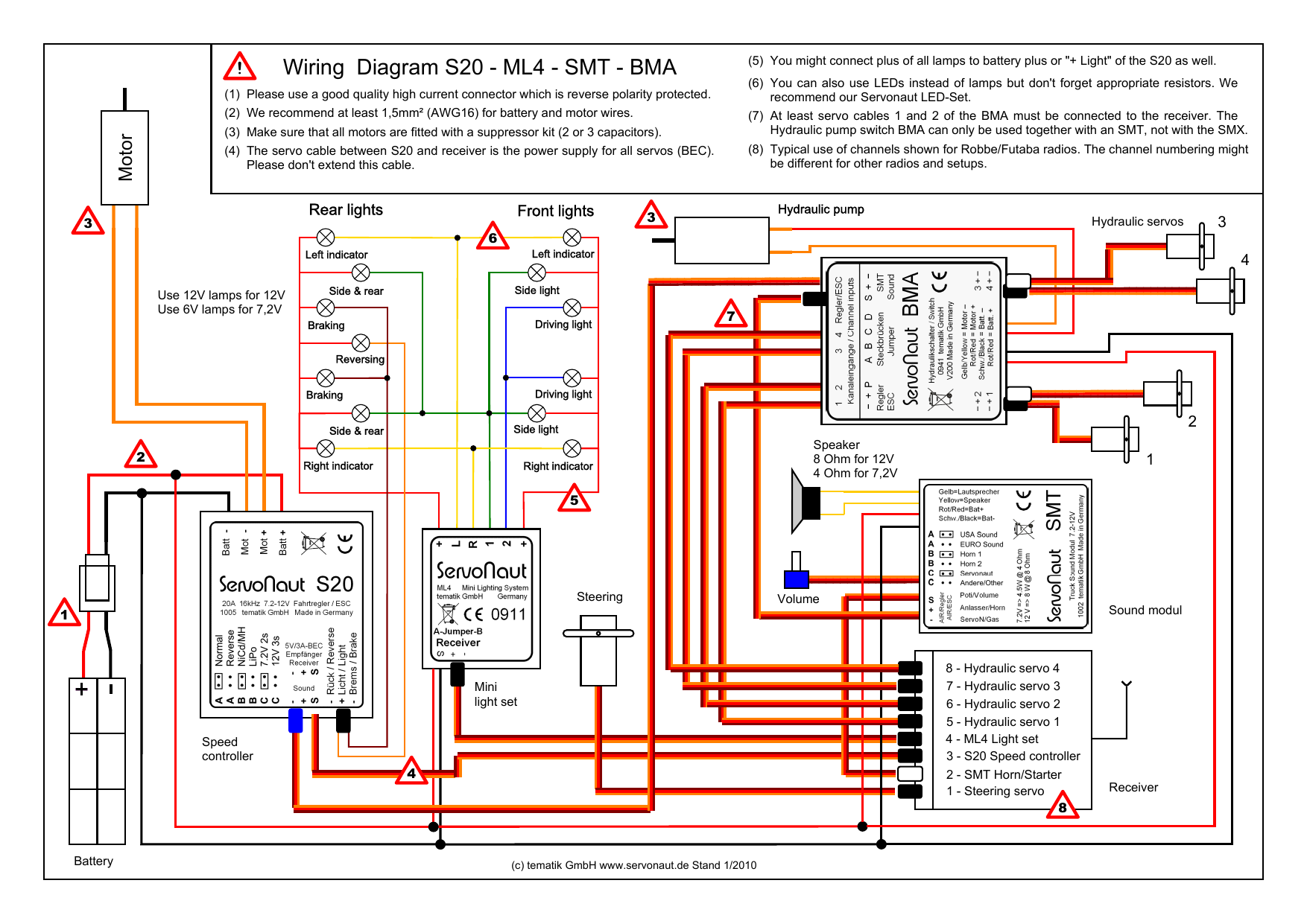
Wiring Diagram S20 Ml4 Smt Bma Manualzz
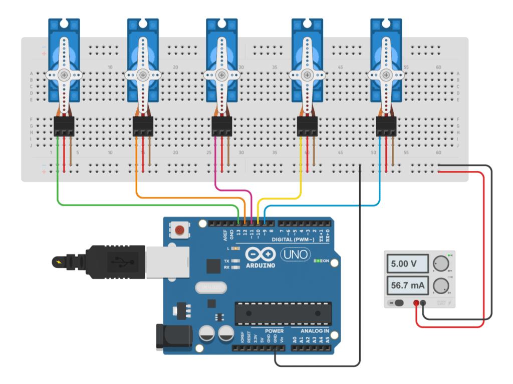
How To Control Servo Motors With Arduino 3 Examples

Wiring Diagram Of The Electronic Components Of The Quadcopter Electrical Engineering Blog Electronic Engineering Mechatronics Arduino Projects
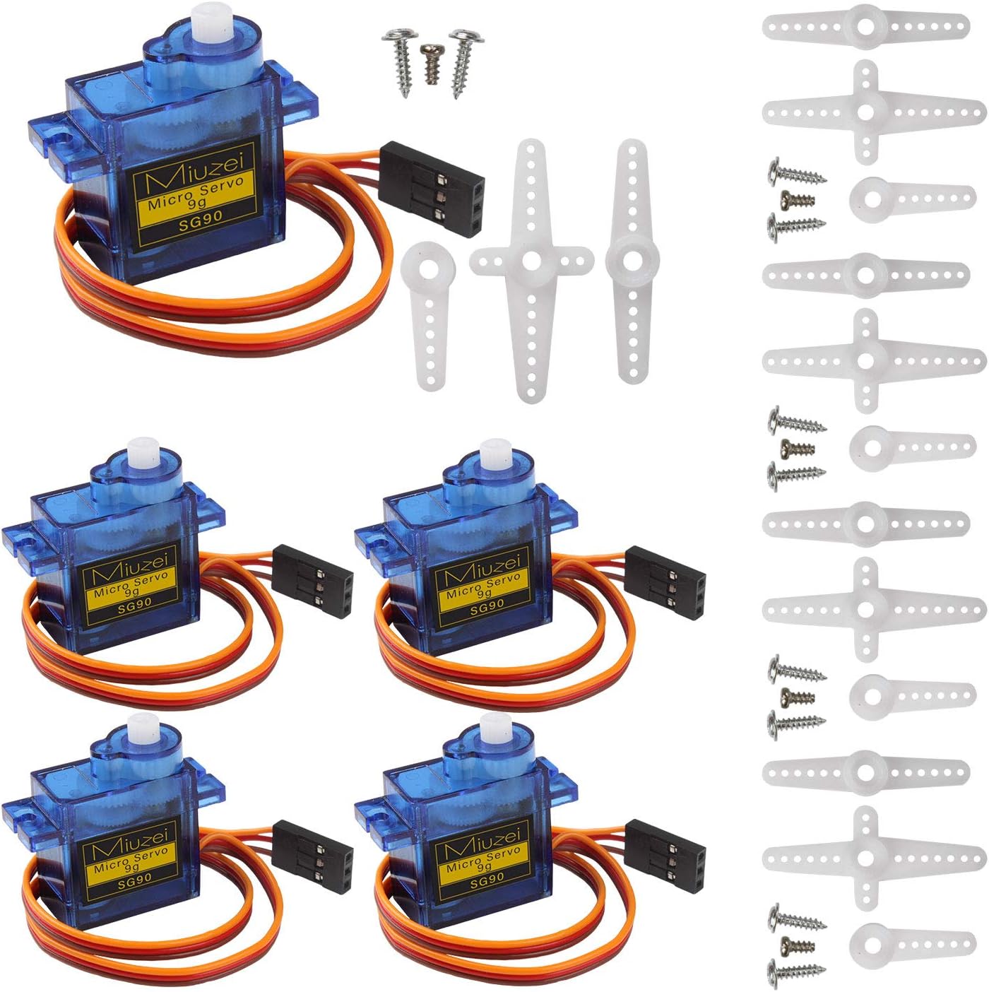
Amazon Com Miuzei 5 Pcs Sg90 Servo Motor Micro Servo 9g Mini Servo Motor For Rc Helicopter Airplane Car Boat Robot Arm Hand Walking Servo Door Lock Control With Cable Compatible With Arduino Toys Games
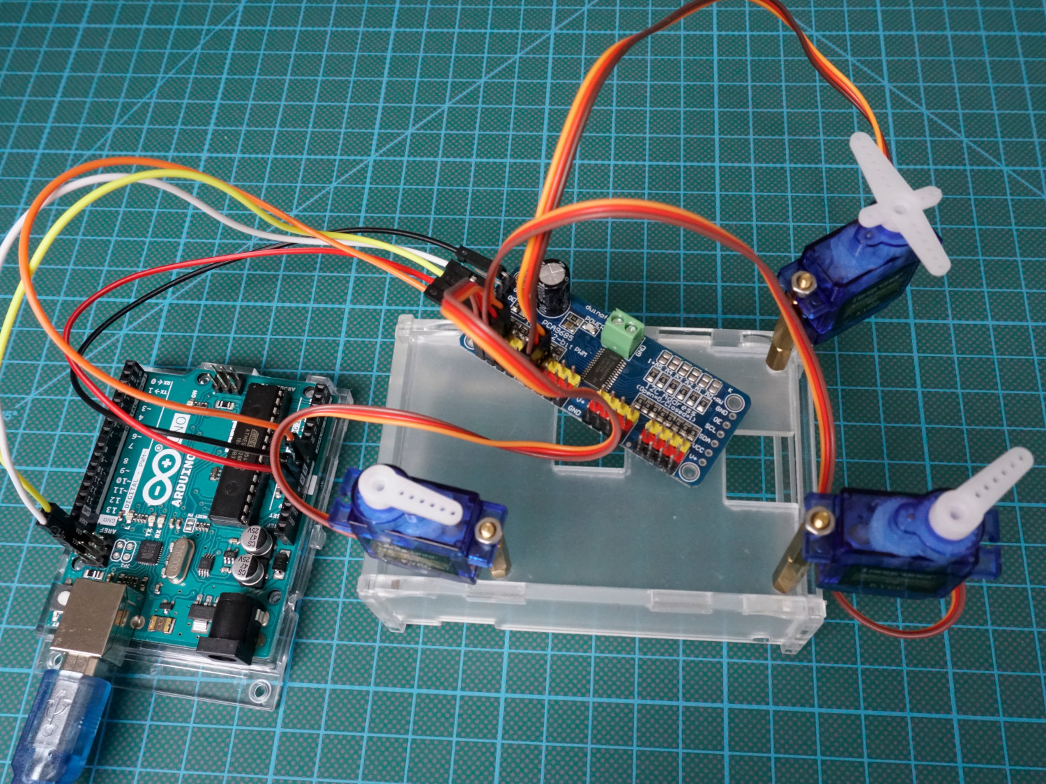
Servo Motor Tutorial For Arduino Esp8266 And Esp32 Diyi0t
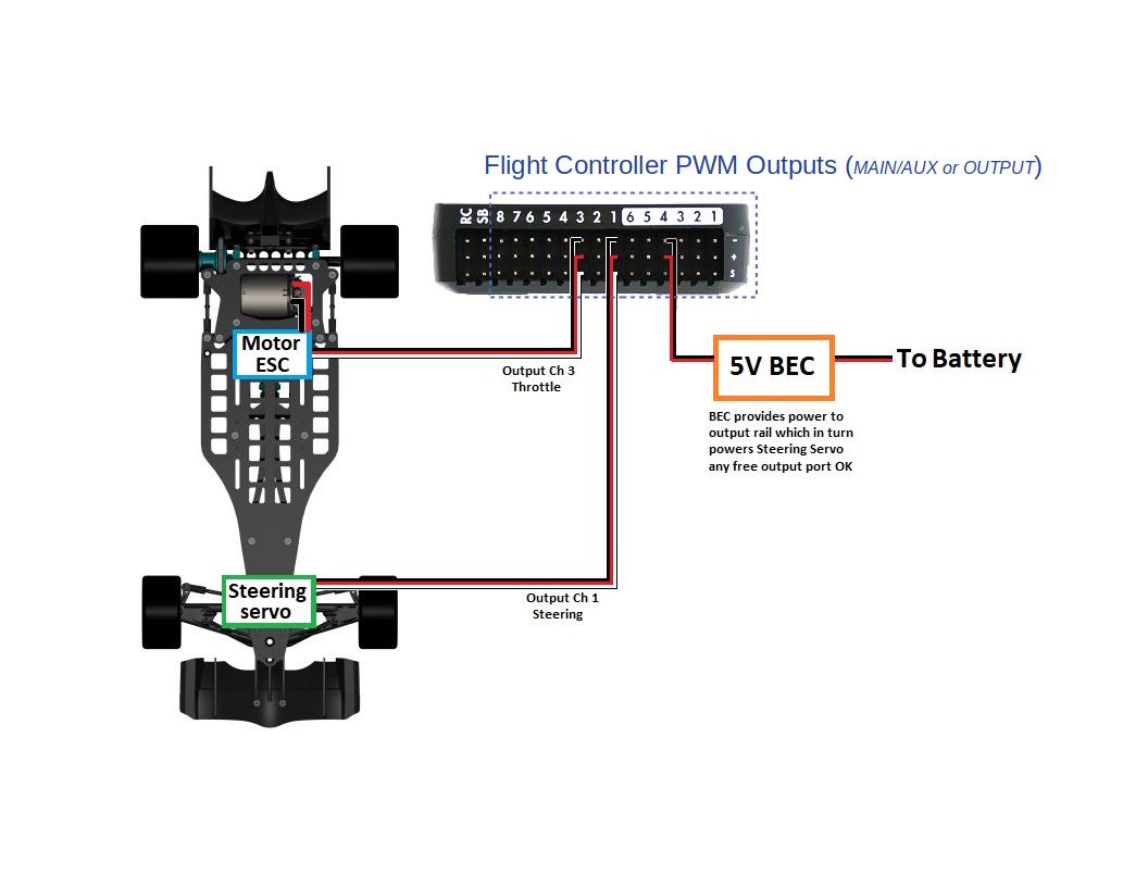
Typical Autopilot Wiring Connections Rover Documentation
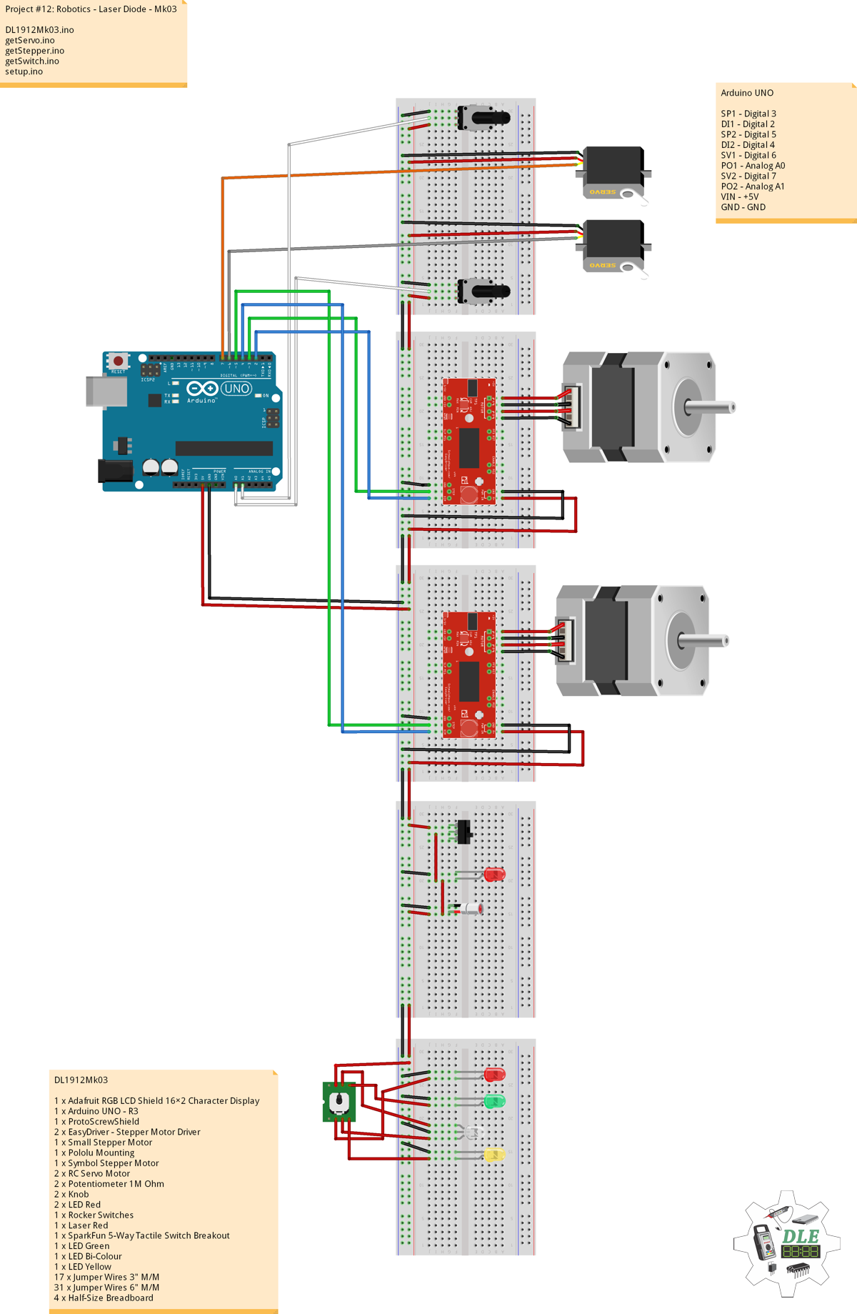
Project 12 Robotics 5 Way Switch Mk04 Arduino Project Hub

Pin On Rc 1 6

Yx 4602 Arduino Board Layout Usb Wiring Diagram Wires Rc Receiver Diagram Schematic Wiring

Diagram Mitsubishi Servo Motor Wiring Diagram Full Version Hd Quality Wiring Diagram Roomyreaction Pumabaskets Fr

How To Make Rc Plane With Arduino And Nrf24l01

Servo Motor Pin Connection In 2020 Arduino Volatile Memory Control Unit
