Ceiling Occupancy Sensor Wiring Diagram
Download Diagram Line Voltage Occupancy Sensor Wiring Diagram Full Version Hd Quality Wiring Diagram Okcwebdesigner Kinggo Fr

Sv 4413 Ceiling Motion Sensor Wiring Diagram Download Diagram

Installation Instructions Passive Infrared Ceiling Mounted Line Voltage Occupancy Sensor Model Oac P 0500 Mv

Download Diagram Watt Stopper Occupancy Sensor Wiring Diagram Full Version Hd Quality Wiring Diagram Okcwebdesigner Kinggo Fr
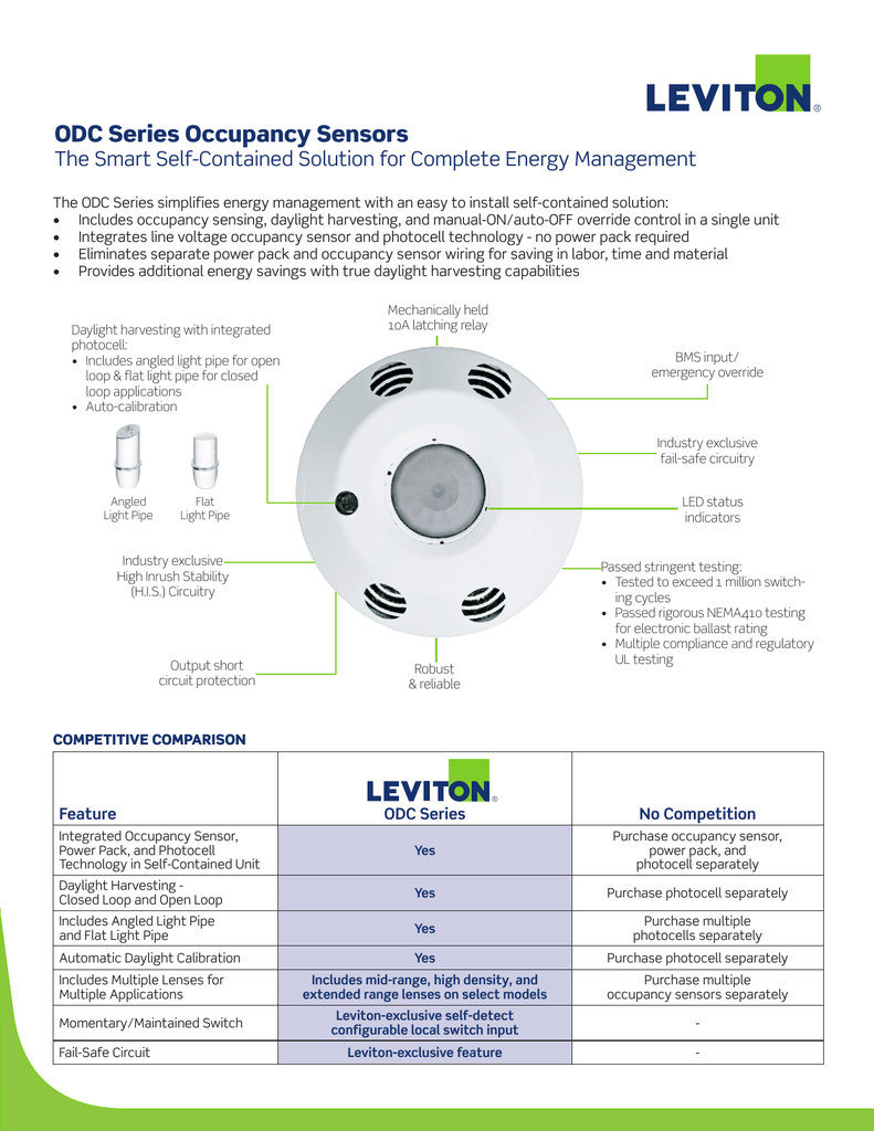
Odc Series Occupancy Sensors

Gm 4912 Ceiling Motion Sensor Wiring Diagram Free Diagram

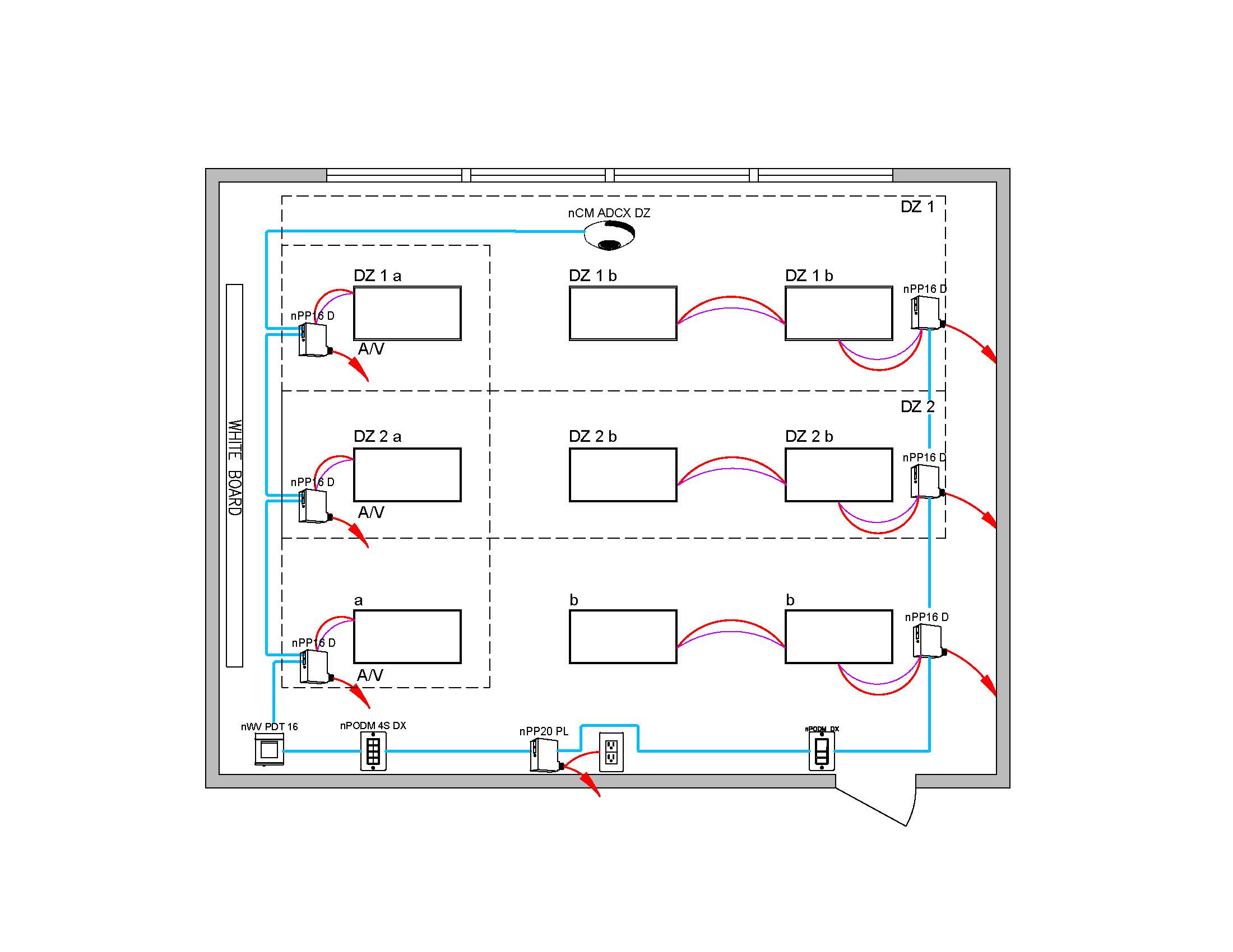
Assortment of ceiling mount occupancy sensor wiring diagram.
Ceiling occupancy sensor wiring diagram. Literally a circuit is the course that permits power to flow. It shows the components of the circuit as simplified forms and also the power and signal links in between the tools. Occupancy sensor switch wires each have two black wires or one black and one red and ground green. Assortment of ceiling occupancy sensor wiring diagram.
A wiring diagram is a simplified conventional pictorial depiction of an electrical circuit. A wiring diagram is a streamlined standard pictorial representation of an electrical circuit. Getting from point a to point b. It reveals the components of the circuit as simplified forms as well as the power and signal links in between the tools.
Each black wire can be a line or a load. Install back cover of the ceiling sensor to the wallboard or drop ceiling using the included screws nuts and washers or screws in combination with commercially available wall anchors. September 30 2018 by larry a. Occupancy sensor ceiling mounted multi technology 24vdc 30ma power exit connect gray wire for photocell ambient light hold off degree harmonic leviton occupancy sensors wiring diagram car diagrams source.
Twist strands of each lead tightly and with circuit. Occupancy sensor wiring diagram 1. One of the black line wires connects to line voltage from the panel the other black or red load wire connects to the light s. November 10 2018 by larry a.

Diagram Ge Sensor Wiring Diagram Full Version Hd Quality Wiring Diagram Thebookbag Esthaonnatation Fr

Electrical Diagram Drawing Tool Diagram Diagramtemplate Diagramsample

Robot Check Sensor Night Lights Motion Light Switch Motion Sensor

Dimmable Slim Led Downlight 4 Inch3000k White11w65w Equilvalent750lm Cri80etl Listed Recessed Lighting Retrofit With Downlights Junction Boxes Recessed Ceiling

Unique Wiring Diagram Backup Generator Diagram Diagramtemplate Diagramsample Check More At Https Servisi Co Wiring Diagram Backup Generator

Wiring Outlets And Switches The Safe And Easy Way Home Electrical Wiring Wire Switch Diy Electrical

Sensky High Sensitivety 360 Degree 110v 220v Ac Automatic Ceiling Infrared Pir Motion Sensor Led Light Switch 037 Motion Sensor Sensor Led Light Switch

Makes Sense Building Sensors For Improved Energy Leviton Save Energy Green Business

8 Pack Bioluz Led 5 6 Inch 75 Watt Uses 12w 90 Cri Dimmable Led Retrofit Recessed Lighting Fixture 30 Recessed Lighting Led Recessed Lighting Dimmable Led
Intehome 16a Smart Home Wifi Switch Wireless Remote Control Alexa Relay Switch For Household Appliances Compat In 2020 Household Appliances Alexa Echo Remote Control

Securitall Offers Brand New Hd 1080p Ip Indoor Dome Surveillance Camera White Surveillance Camera Motion Sensor Lights Outdoor Best Waterproof Camera

Lyric T5 Wi Fi Thermostat Works With Amazon Alexa The Lyric T5 Thermostat Allows You To Tak Honeywell Wifi Thermostat Smart Thermostats Honeywell Thermostats

Lutron Maestro Motion Sensor Switch 2 Amp Single Pole White 2 Pack Ms O2s 2pk Wh The Home Depot Motion Sensor Lutron Tv Cord Cover
