Defi Tachometer Wiring Diagram

Installation For Installation Personnel Warning Caution Defi Link Vsd Concept User Manual Page 3 16
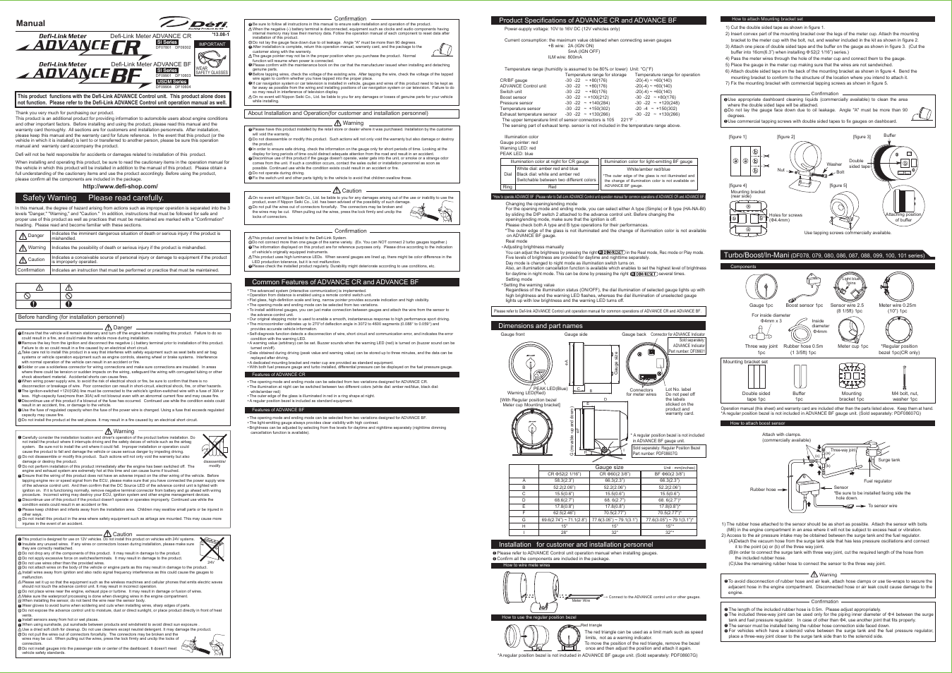
Defi Advance Bf Except Tachometer User Manual 2 Pages Also For Advance Cr Except Tachometer
Defi Advance Bf Tachometer User Manual 1 Page Also For Advance Cr Tachometer
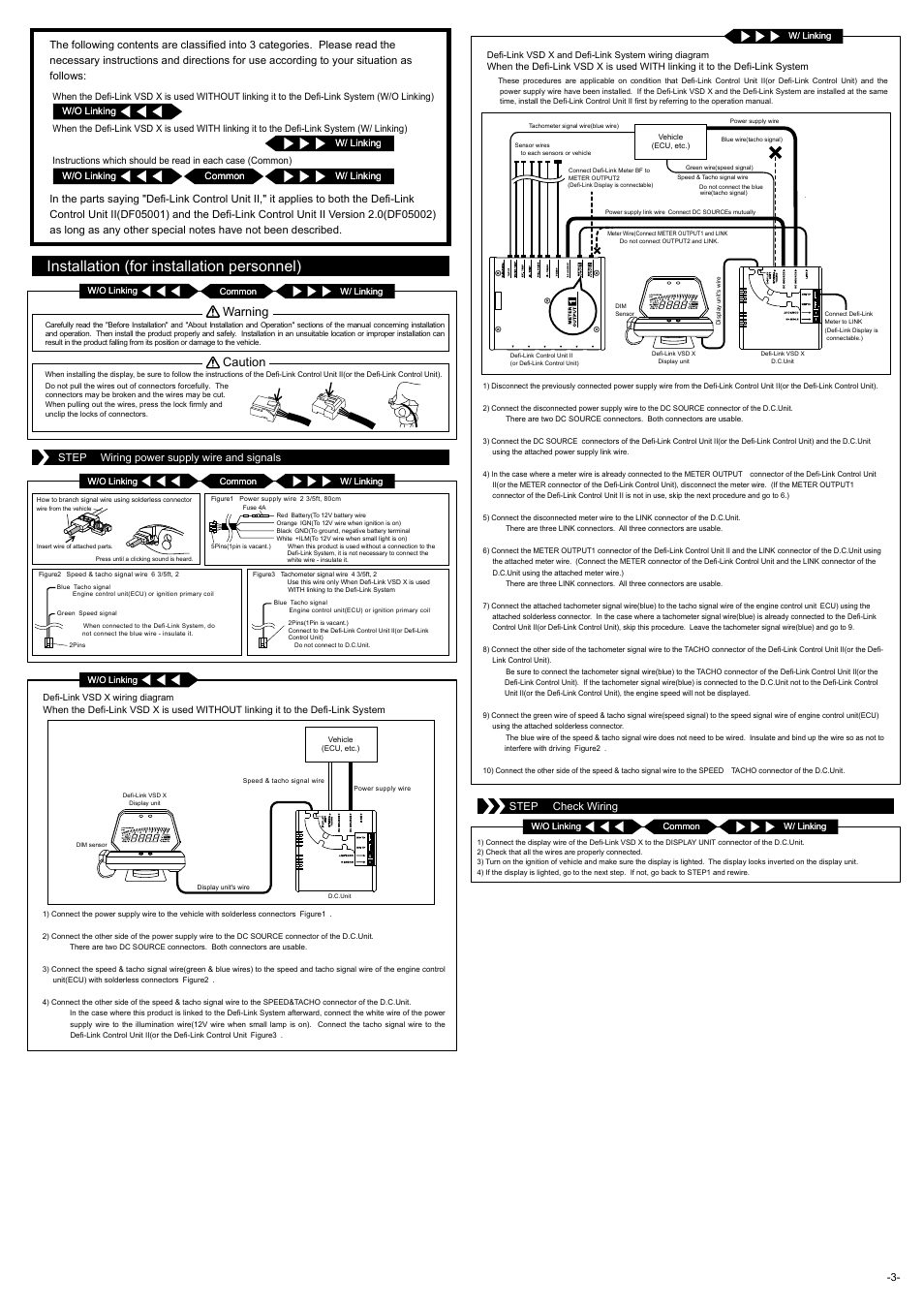
Installation For Installation Personnel Warning Caution Defi Link Vsd X User Manual Page 3 6

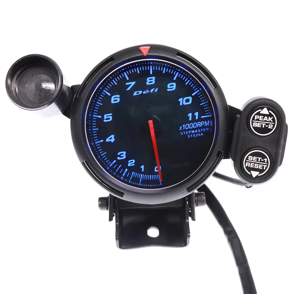
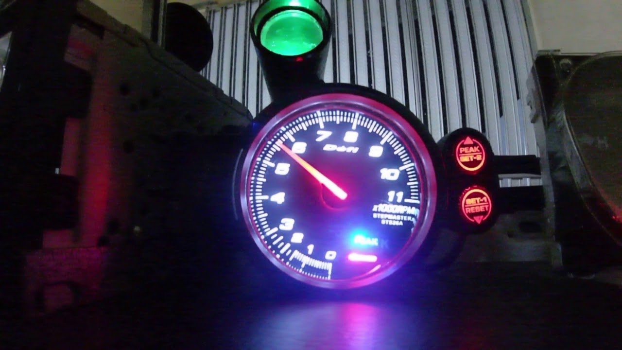
Defi Racer Gauge 80mm Tachometer Youtube

Defi Advance Link System Zd 6 Daisy Chain Gauges Bf Cr Rs C2 Volt Water Temp Oil Temp Oil Press Tachometer Rpm Turbo Boost Gauge Aliexpress
Defi link control unit first model.
Defi tachometer wiring diagram. The wiring diagram shown is a typical installation. The system is also designed to allow all sensors to be attached to the control unit ii so that gauges can be mounted. Defi 80mm 11000 rpm tachometer advance system connection exciting products by ns an link draw your wiring meter diagram tein usa blog vd 0473 gauge get free image about drawing at paintingvalley com explore collection of instructions bugsandbuggies features gauges how to install egauges defi 80mm 11000 rpm tachometer advance system connection defi exciting products by ns an read more. Advance system connection the defi link advance system allows gauges and displays to be attached to the advance control unit with a single daisy chain wiring system.
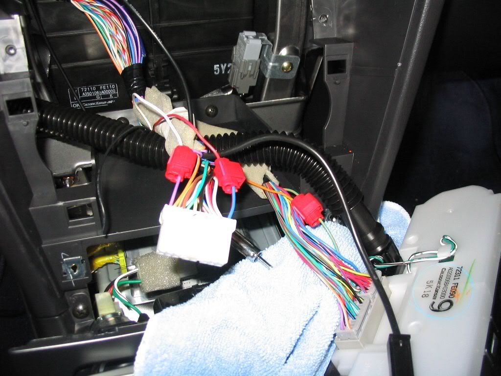
Advance gauges displays and control unit are equipped with microcomputers. Variety of autometer tach wiring diagram. Connect a wire from pin 5 to a constant 12 or 24 volt source. Defi link meter bf defi link meter defi link control unit ii.
A wiring diagram is a streamlined standard pictorial representation of an electrical circuit. Product name end of production amount of pages. 12v battery coil ignition coil tach base can be mounted in either direction for convenient mounting. A switched 12 or 24 volt wire can be found coming from the ignition switch.
Distant gauges and displays can be operated at hand. Follow this wire to a junction and attach the wire from pin 4 at this junction i e. Racer gauge tachometer bf tachometer. It reveals the components of the circuit as simplified shapes and also the power and also signal connections in between the devices.
Connect the wire from pin 4 to a switched 12 volt or 24 volt source. Part name quantity gauge 1 switch unit wire 45cm 1 48ft 1 regular position bezel 1 back case 1 mounting band 1 mounting rubber 1 power supply tachometer signal wire 2 2m 7 2ft 1 indicator wire 20cm 7 8in 1 operation manual 1 terms and conditions 1 mounting bracket 1 attachment for switch unit 1 m6 bolt 2 spring lock washer 2 washer 2. Defi link system connection the defi link system allows gauges and displays to be attached to the control unit ii with a single daisy chain wiring system. For chrysler blue gold and silver boxes ford standard electronic ignitions and most other oem standard cd and electronic ignitions.
Distant gauges can be operated at hand. Defi link display vsd concept and defi link system wiring diagram 1 disconnect the previously connected power supply wire from defi link control unit ii or defi link control unit. Racer gauge 80 tachometer. Refer to diagram d.
The system is also designed to allow all sensors to be attached to the advance control unit so. Defi link system connection exciting products by ns an how to install boost gauge my pro street advance din rookie wiring questions racer rx7club com mazda rx7 forum tein usa blog instructions bugsandbuggies d gauges egauges sensor specification a tachometer onallcylinders defi link system connection exciting products by ns an how to install defi boost gauge my pro read more. Gaugess displays and control unit ii are equipped with microcomputers.

Aftermarket Defi Tacho Install Advise Scoobynet Com Subaru Enthusiast Forum

Need Help To Install Defi Vsd On Srt8 Chrysler 300c Srt8 Forums

Defi Advance System Daisy Chain Auto Gauge Zd 6 Gauges Advance Bf Volt Water Temp Oil Temp Oil Press Tachometer Rpm Turbo Car Turbo Gauge Defi Cars Carszd Gauge Aliexpress
Gauge Installation Electrical Wiring Tips And Pics Defi And Others Nasioc

Structure Volt Gauge Wiring Diagram Picture Full Version Hd Quality Diagram Picture Okcwebdesigner Kinggo Fr
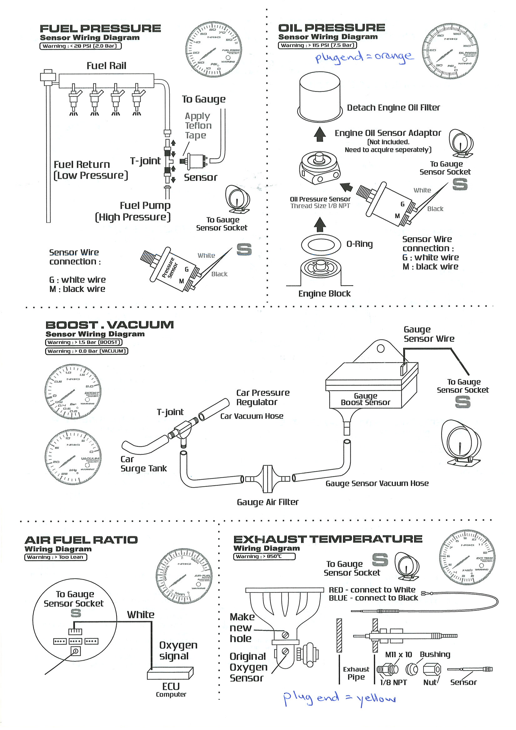
Diagram 370z Aftermarket Wiring Diagram For Full Version Hd Quality Diagram For Fourstarengine Pumabaskets Fr
Waterproof 80mm Car Tachometer Tach Meter 0 11000 Rpm Auto Gauge With Shift Light Work For 1 10 Cylinders Engine Tachometers Aliexpress

Defi Tachometer Gauge 7 Colors 0 11000 Rpm Shift Light Bf Style Auto Pointer Gauge Saat Meter 72mm Aliexpress
Setting Tachometer Defi Youtube
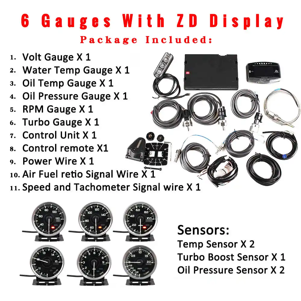
Defi Advance A1 Defi Link System Daisy Chain Auto Gauge Zd 6 Gauges Volt Water Temp Oil Temp Oil Press Tachometer Rpm Turbo Aliexpress

Diagram Amplifier Wiring Diagrams Wiring Diagram Full Version Hd Quality Wiring Diagram Safetywiring Defi Gym Fr
Defi Tach 2 Blue Wires Honda Tech Honda Forum Discussion

Bluetooth Wifi App Control Obd Lcd Auto Gauge Lcd Obd Sensor Plug N Play App Bluetooth In 2020 Car Gauges Lcd Obd
