Intermatic Pool Pump Timer Wiring Diagram

How To Wire Intermatic T104 And T103 And T101 Timers

Contactor Wiring Diagram With Timer Diagram Diagramtemplate Diagramsample Timer Wire Diagram
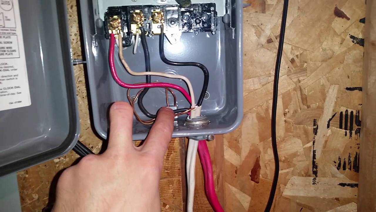
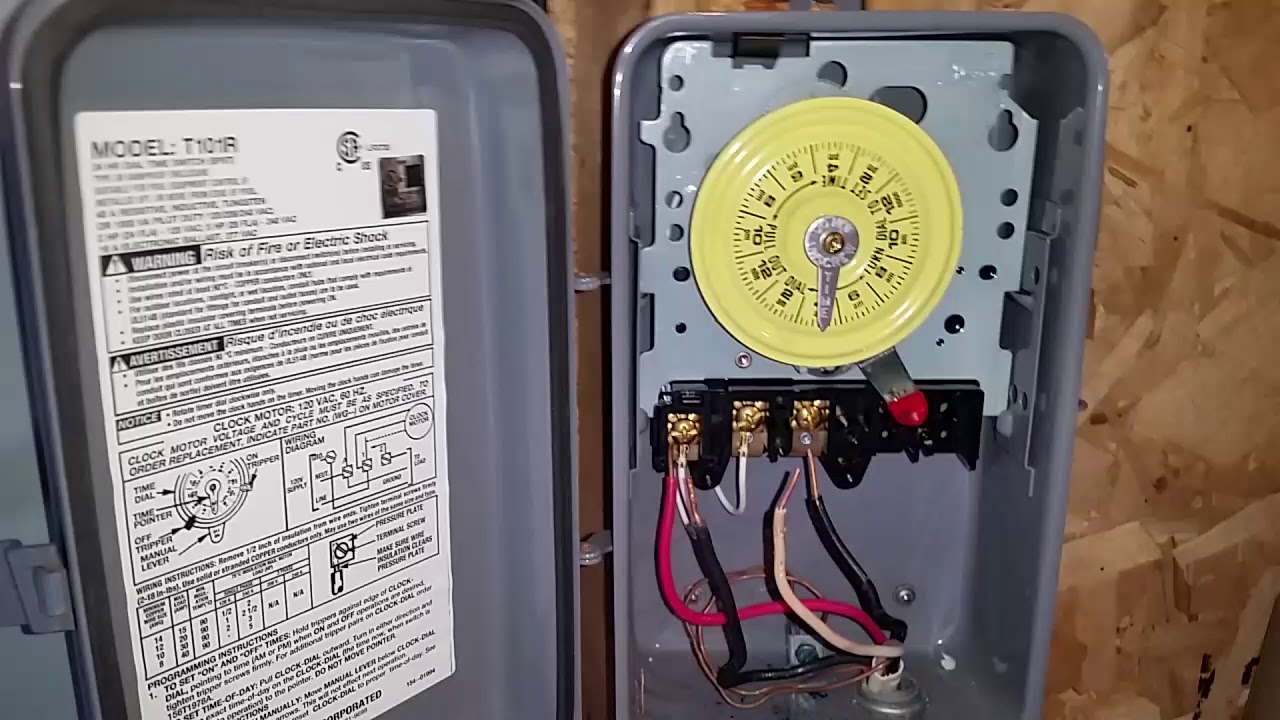
How To Wire And Connect A Intermatic Pool Pump Timer T101r Youtube
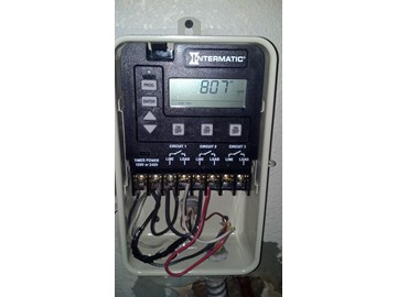
How To Wire A Pe153 Digital Timer To A 2 Speed 230v Motor Inyopools Com
How To Wire Connect Intermatic Pool Pump Timer Simple Short Video Youtube

Http Waterheatertimer Org How To Wire T104 Intermatic Timer Html Diy Water Pool Light Diy Electrical

Many pool pump motors and water heaters use intermatic timers to regulate their run times.
Intermatic pool pump timer wiring diagram. Assortment of intermatic t103 wiring diagram. A wiring diagram is a sort of schematic which makes use of abstract pictorial icons to show all the interconnections of parts in a system. Click on the image to enlarge and then save it to your computer by right clicking on the. Intermatic pool timer wiring diagram intermatic pool timer wiring diagram fresh fine pool pump timer wiring diagram gallery electrical and wiring.
Intermatic t103 wiring diagram download fresh intermatic pool timer wiring diagram irelandnews. Fresh intermatic pool timer wiring diagram irelandnews. Lighting contactor wiring diagram with cell rc2163e control. A wiring diagram is a streamlined traditional pictorial representation of an electric circuit.
A pool pump timer interrupts the electric circuit powering the pump motor during off use periods. How to wire intermatic t104 and t103 t101 timers adorable pool pump what s wiring diagram. The word date and a number will be flashing for a two switch setup 3 way when reusing the existing 3 way fig. An intermatic timer switch saves electricity when it turns a water heater off at night and when it limits the amount of time.
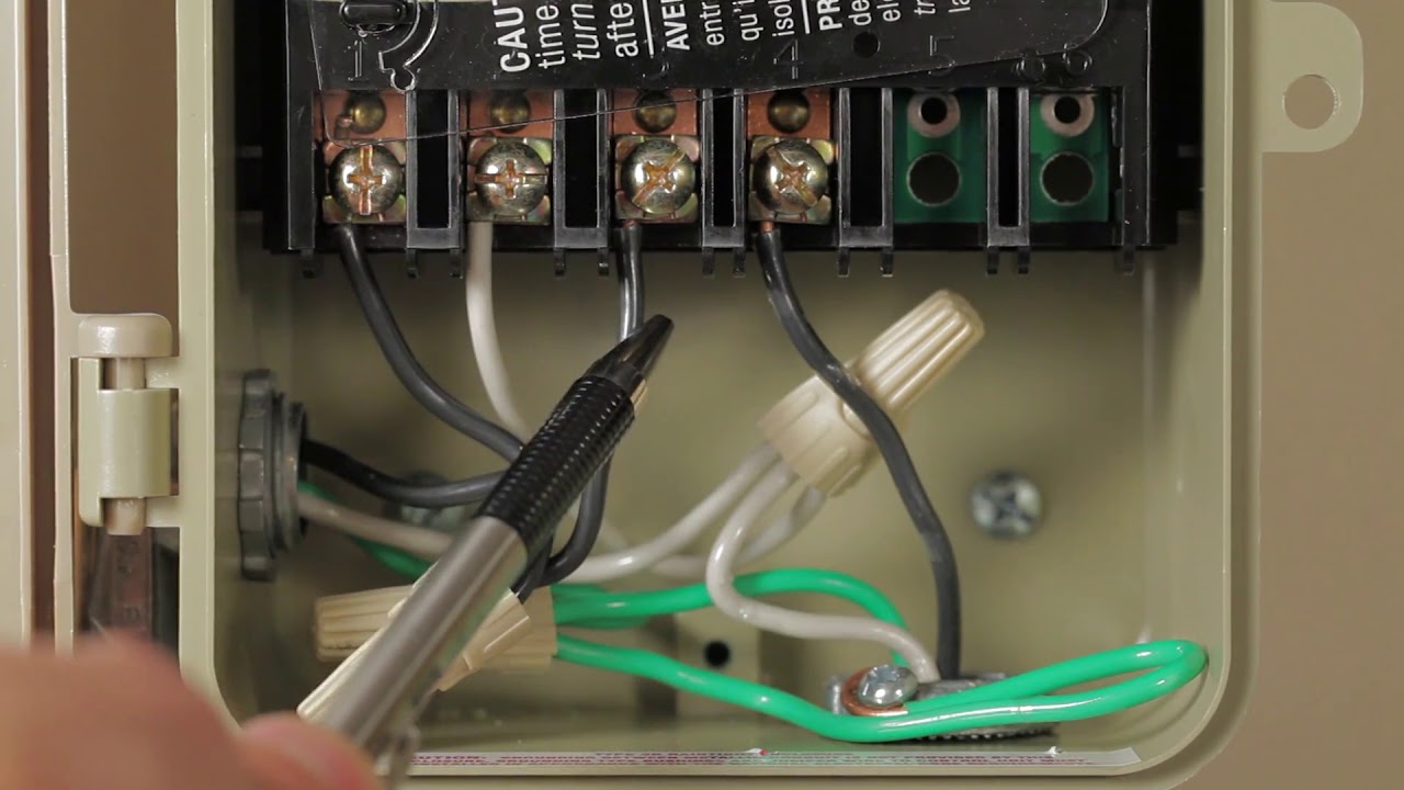
Intermatic incorporated manufactures timer switches designed for indoor and outdoor use. Intermatic cell wiring diagram best 06 intermatic et1125. Press next on off to display the date. Wiring diagrams for multiple switch timer setups.
Intermatic 240v timer wiring diagram how to wire and connect a intermatic pool pump timer in wiring diagram. It shows the elements of the circuit as streamlined shapes as well as the power as well as signal links between the devices. Variety of intermatic 240v timer wiring diagram. Many pool pump motors and water heaters use intermatic timers to regulate their run times.

Unique Wiring Diagram For Amp Gauge Diagram Diagramtemplate Diagramsample
Tork Wiring The E Series Timers For 120 Volts Youtube

This Post Is About The Staircase Timer Wiring Diagram In The Diagram I Use The On Delay Timer Finder 8 Pin Relay Re Electrical Circuit Diagram Timer Diagram
Diagram Oven Timer Wiring Diagram Full Version Hd Quality Wiring Diagram Kigrafik Msc Lausitzring De

Eh40 30 Amp 7 Day Timer Http Waterheatertimer Org How To Wire Eh40 Hot Water Heater Timer Html Water Heater Diy Water Heater

Standard Wire And Color Codes Gary S Garagemahal The Bullnose Bible In 2020 Coding Color Coding Diagram

Step Down Transformer Thermostat Wiring Color Coding Coding

How To Change A Primer Bulb On A Husqvarna Chainsaw Amazon Vender Bulb Chainsaw Husqvarna

Carga Refrigerante Por Peso En Equipo Split Metodo I Refrigerante Ar Condicionado

12 Best Air Conditioner Brands 3 In 2020 Air Conditioner Brands Air Conditioner Conditioner

Forced Manual Defrost Mode On A Samsung Refrigerator Top Secret Setting Samsung Refrigerator Samsung Fridge Refrigerator Repair
