Mk Fused Spur Wiring Diagram

New Mk Emergency Key Switch Wiring Diagram Diagram Diagramsample Diagramtemplate Wiringdiagram Di Light Switch Wiring 3 Way Switch Wiring Three Way Switch
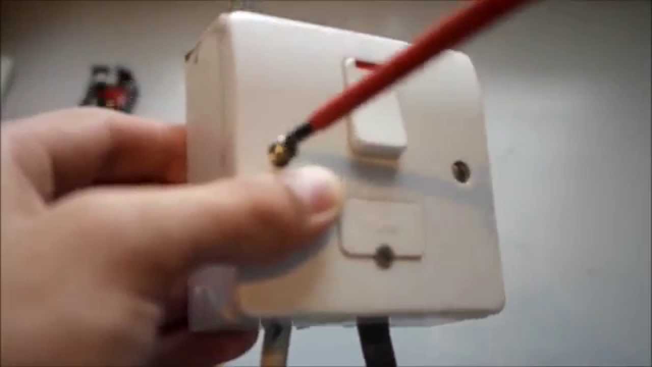
How To Wire An Fcu Fused Connection Unit Youtube
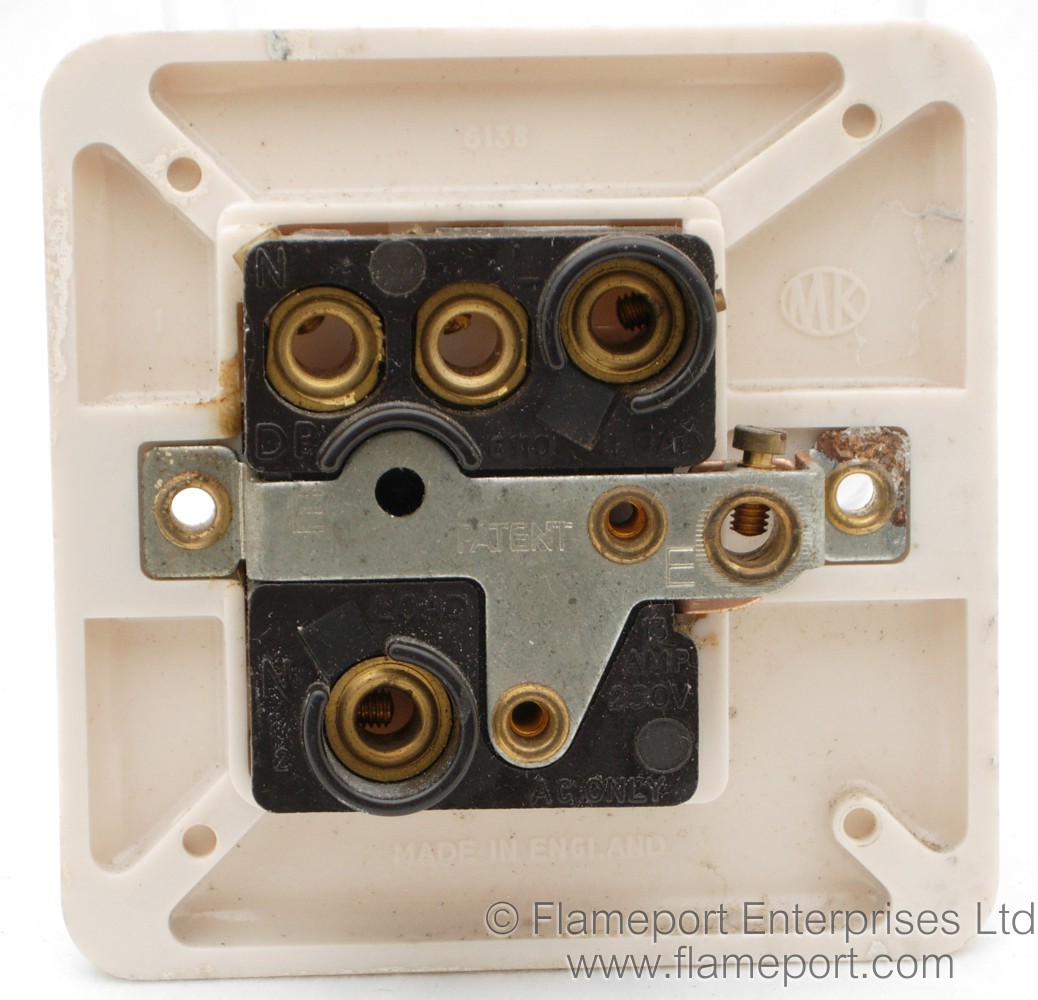
Mk 6138 Switched Fused Spur

New Mk Emergency Key Switch Wiring Diagram Diagram Diagramsample Diagramtemplate Wiringdiagram Diagramchart Wor Electrical Diagram Diagram Diagram Design

New Mk Emergency Key Switch Wiring Diagram Diagram Diagramsample Diagramtemplate Wiringdiagram Light Switch Wiring Thermostat Wiring Honeywell Thermostats
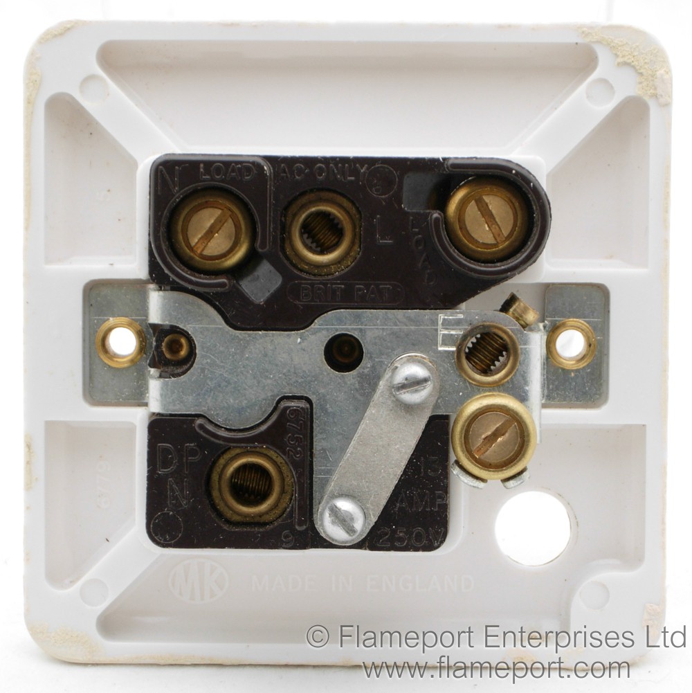
Mk 6779 Switched Fused Spur

7 when connecting the new accessory ensure that only the bare end of the wire enters the terminal and no bare wires are visible.
Mk fused spur wiring diagram. Connect the cables as in the diagram ensuring that the load cable is connected to the appliance in use. 3 way intermediate switch to touch dimmer conversion wiring. Fused spur wiring diagram in conjunction with the touch4 programmer. The first image is how the back of your double socket should look and the second is the wiring for a spur.
3 way touch dimmer wiring. Mk mk electric mk electrical mk switches mk electrical products mk sockets mk electrics mk logic plus mk logic mkelectric. Wiring devices technical. 20a switch as a.
2 way touch dimmer wiring. Socket outlets switches and other mk wiring accessories can be mounted in a variety of mk trunking systems. Fuse carriers logic plus 3 gang switchsocket only the fuse carrier is opened by a fast acting screwdriver operated worm drive screw. The spur must be connected to the existing circuit using the same cable as used in the main circuit.
It goes around the house or a room and connects to all the sockets and fused connection units fcu s required to be on the ring main circuit. A suitable means of local isolation of the radiator from both the electrical supply and the pilot wire signal must be provided. Uk wiring only may not be the same in your country so you must check with your local building regulations. How to install a fused spur.
442 wiring devices mkelectric co uk. This is achieved by connecting the fixed earth wire to the earth terminal on the socket or switch and then connecting a short length of wire. Fitted with a 13 amp fuse. Ledfix glowfix or yagf p wiring.
5 carefully arrange the wiring to lie along the edges of the product or box keeping the central area clear. If in any doubt on how to. 3 way intermediate switch dimmer wiring. Hi in this video i d like to show various samples of installing 13 amp fcu fused connection unit often used as a fused spur in a ring final circuits.
How to wire an fcu safely. As you can see the circuit starts and ends at the consumer unit. You can see how to wire a spur to an existing socket from the images below. Please observe the wiring diagram above.
When connected to the touch4 select the automatic operation mode on the electric décor or column rf thermostat.

Spridgetguru Com Tech Index Fuel Gauge Wiring Diagram

Unique Wiring Diagram For Mk Garage Kit Diagram Diagramsample Diagramtemplate Wiringdiagram Diagramchart Worksheet Worksheettempla Diagram The Unit Wire

Unique Wiring Diagram For Mk Garage Kit Diagram Diagramsample Diagramtemplate Wiringdiagram Diagramchart Wo Electrical Wiring Diagram Diagram Boat Wiring

Wiring Diagram Dual Rcd Consumer Unit New Mk Rcd Wiring Diagram Carbonvotedit Consumers The Unit Home Electrical Wiring

Unique Wiring Diagram For Mk Garage Kit Diagram Diagramsample Diagramtemplate Wiringdiagram Diagramchart Worksheet Wor Garage Kits Diagram Chart Diagram
New Mk Emergency Key Switch Wiring Diagram Diagram Diagramsample Diagramtemplate Wiringdiagram Diagramchart Worksheet Workshe Diagram Wire Diagram Chart

New Mk Emergency Key Switch Wiring Diagram Diagram Diagramsample Diagramtemplate Wiringdiagram Diagramchart Worksheet Diagram Chart Ford Tractors Diagram

Mk3 Sprite Wiring Diagram Austin Healey Sprite Austin Healey Diagram
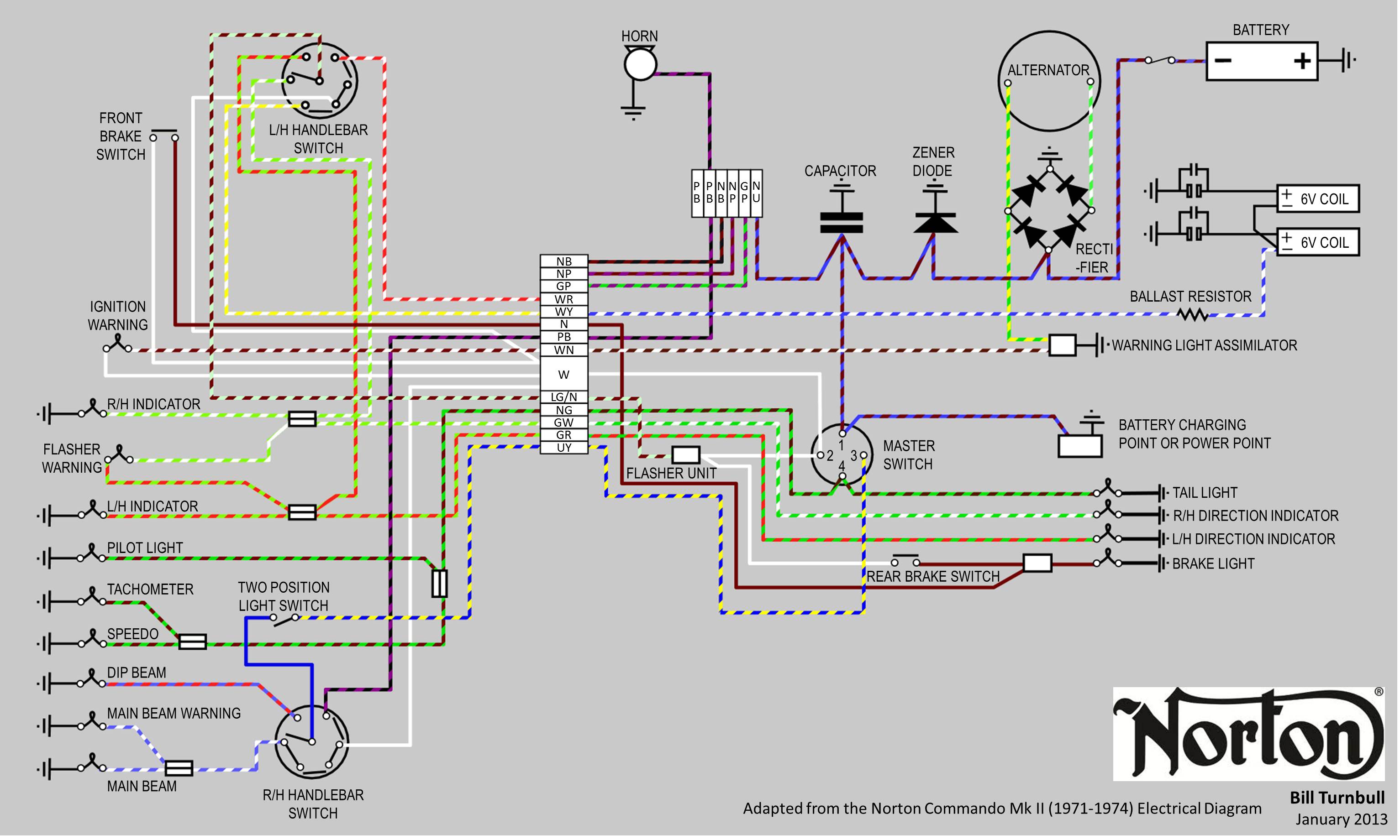
1966 Norton Wiring Diagram Full Version Hd Quality Wiring Diagram Tixadiagram As4a Fr

New Golf 4 1 9 Tdi Wiring Diagram Diagram Diagramsample Diagramtemplate Wiringdiagram Diagramchart Worksheet Worksheettemplate Vr6 Engine Vw Up Tdi

Spitfire Mkiv Wiring Diagram Triumph Spitfire Triumph Fuse Box

New Mk Emergency Key Switch Wiring Diagram Diagram Diagramsample Diagramtemplate Wiringdiagram Diagramchart Worksheet Wo Diagram Diagram Design Tekonsha

New Golf 4 1 9 Tdi Wiring Diagram Diagram Diagramsample Diagramtemplate Wiringdiagram Diagramchart Worksheet Worksheettemplate Diagram Vw Beetles Tdi
