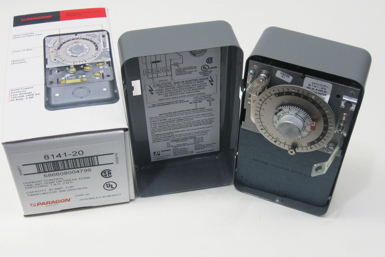
Model 8145 20 Wiring Diagram

Paragon defrost timer wiring diagram paragon defrost timer wiring regarding 8145 20 wiring diagram image size 577 x 600 px and to view image details please click the image.
Model 8145 20 wiring diagram. Paragon 20 wiring diagram wiring diagram pdf free paragon 20 wiring diagram in addition defrost timer wiring diagram further diagram model tr timer along with paragon defrost control 26x also defrost read more at. 8145 20 208 240 none open closed bracket available and 50 hz. Paragon 8145 00 wiring diagram timer wiring diagrams wiring harness wiring diagram wiring wire rh linxglobal co. 6 days ago november 22nd i have a paragon 20 defrost timer do you wire the compressor to the timer i cant seem to find a wiring diagram on.
Click on the image to enlarge and then save it to your computer by right clicking on the image. Paragon timer models and. The paragon defrost and the tork electric timers offer versatility and unbeatable electric heat. Electric heat defrosting models 8141.
Paragon timer models and. Models 8145 00 and 8145 20 cycle 1 2 normally closed thermostat used with defrost heater. Click on the image to enlarge and then save it to your computer by right clicking on the image. Hot gas or compressor shutdown.
Download 8145 20 timer wiring diagram. In how to wire the mr4pmuhv to replace the paragon. Wiring diagrams electric heat defrosting s s series. 8145 20 timer wiring diagram.
Paragon 8145 20 wiring diagram. Applications and wiring diagrams mechanical defrost timer 8000 series. 4 to minutes in s and paragon wiring diagrams electric heat defrosting s s series. The usual components in a wiring diagram are ground power supply cord as well as connection outcome devices switches resistors logic gate lights etc.
Here is a picture gallery about 8145 20 wiring diagram complete with the description of the image please find the image you need. Applications and wiring diagrams mechanical defrost timer 8000. Find solutions to your paragon defrost timer 20 wiring diagram question. We hope this article can help in finding the information you need.
Timer wiring diagrams furthermore paragon 8145 20 wiring diagram. Get free help tips support from top experts on paragon defrost timer adjustable defrost cycle duration. Model number time initiated time terminated time initiated temperature. To read a wiring diagram first you need to recognize what basic aspects are included in a wiring diagram and which pictorial signs are made use of to represent them.
27 11 2018 27 11 2018 7 comments on paragon defrost timer 8145 20 wiring diagram. S and paragon available in 6 pack display. A diagram showing how to switch wires from. Wiring using 120v or 240v single phase fine compressor voltage common to timer.


