Pnp Photoelectric Sensor Wiring Diagram

How To Wire Discrete Dc Sensors To Plc Part 2 Plc Programming Courses For Beginners Realpars Plc Programming Sensor Ladder Logic

Abc Arduino Basic Connections Arduino Basic Connection

Protecting Your Io Input Output Using Zener Diode 14core Com Diode Arduino Electronics

Bc547 Transistor Pinout Working And Its Applications In 2020 Transistors Electronics Circuit Bipolar Junction Transistor

Epingle Par Dubai Sensor Sur Products

Diagram Pnp Sensor Wire Diagram Full Version Hd Quality Wire Diagram Envirografik Msc Lausitzring De
A sick wl12 3p2431 photo eye is an excellent example of a basic on off pnp sensor.
Pnp photoelectric sensor wiring diagram. The 0v blue will be attached to the common input and the switching wire black will be attached to the input number. Three wire sensors are used in various applications from detecting parts to locating position of the actual machine. It shows the parts of the circuit as streamlined forms and the power as well as signal links between the devices. A wiring diagram usually provides information concerning the family member setting and setup of devices and terminals on the tools to assist in building or servicing the device.
The sensor has two outputs that may be tied into a programmable logic controller input of the sinking type. Here s a simple way remember how to wire up a 3 wire dc pnp or npn sensor. A wiring diagram is a simplified traditional photographic representation of an electric circuit. Connect all 3 white wires from house from sensor and from light together.
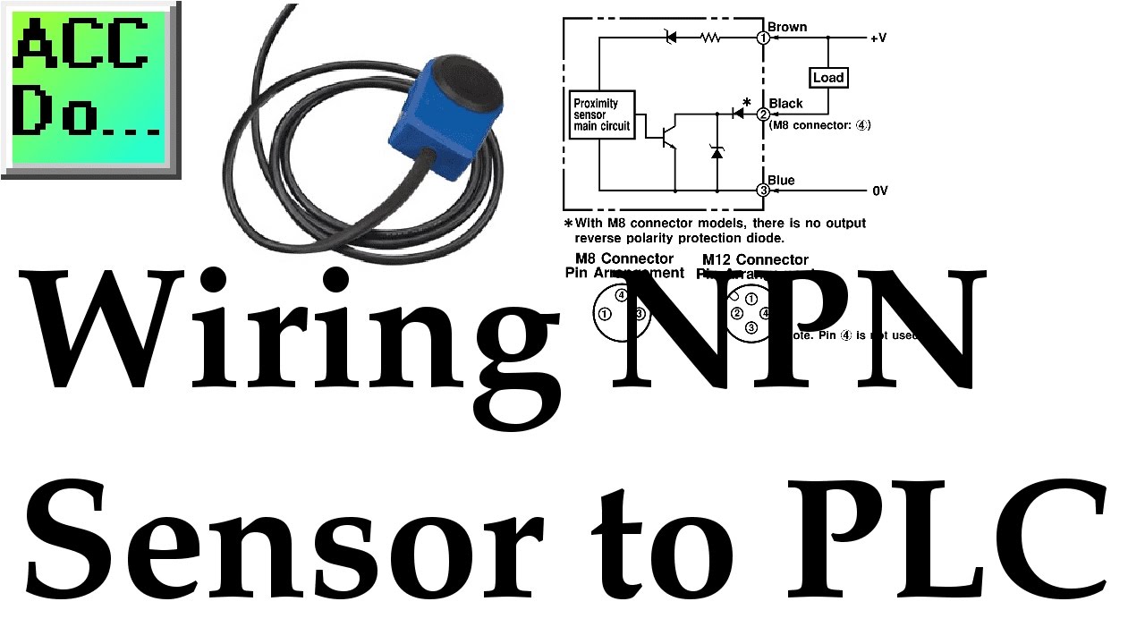
They can come in all different technologies such as inductive photoelectric and capacitive just to list a few although the sensor technology may differ all 3 wire sensors are wired the same a three wire sensor has 3 wires present. When connecting to the plc the plc input acts as the load. 2 wire dc pnp 2 wire dc npn 3 wire dc pnp and 3 wire dc npn cases have been covered in this discussion. The following is a wiring diagram of an open collector pnp sensor.
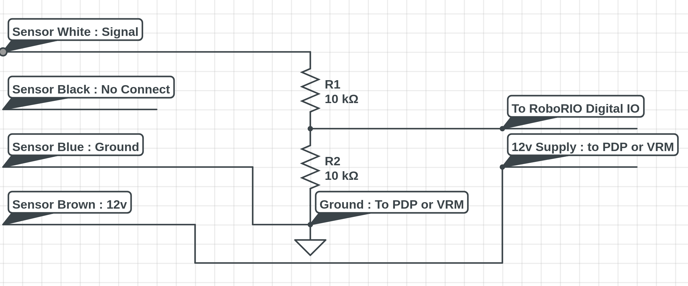
Wiring diagrams mechanical drawings specifications cable exit 4x0 14mm2 ø3 75 mm. Current sourcing pnp outputs are internally connected to the power supply voltage and so should be wired externally to a load that has a connection to dc ground. Connecting a 4 wire dc sensor is the same as a 3 wire sensor but each output wire is connected to a different input on the input card. You will notice that the load appears between the 0v blue and switching wire black.
Pnp receiver 10 30 vdc ov load 100ma 3 bu 1 bn light on n c dark on dark on 2 wh 4 bk npn receiver 10 30 vdc ov. The wiring diagram dictates a standard configuration which requires a 24vdc and gnd signals for power. Connection diagrams for 3 or 4 wire sensors will also show the required wiring configuration for their type of output. Connect sensor s black wire to black wire coming from house.
Because npn sensors sink voltage and pnp sensors source voltage to the plc input npn and pnp sensors should never be mixed on a plc input card. Connect red sensor wire to light s black wire. Either the load is connected to negative and the positive is switched pnp continue reading an easy way to remember pnp and npn sensor. Examples used in this discussion are common setups in modern industry but vary depending on the.
Doing so can lead to an unsafe condition. Black wire is 120 volts so turn off switch or circuit breaker.
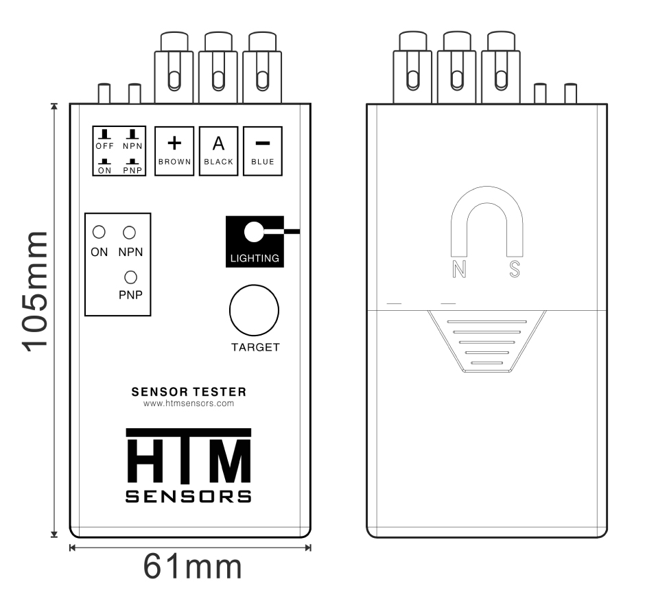
Proximity Switch And Sensor Tester
How To Wire And Program Photoelectric Sensors Beginner Technical Discussion Chief Delphi
Wiring Pnp Sensor To Plc Youtube

Star Delta Schematic By Jhd Electronics Projects Timer Small Camera
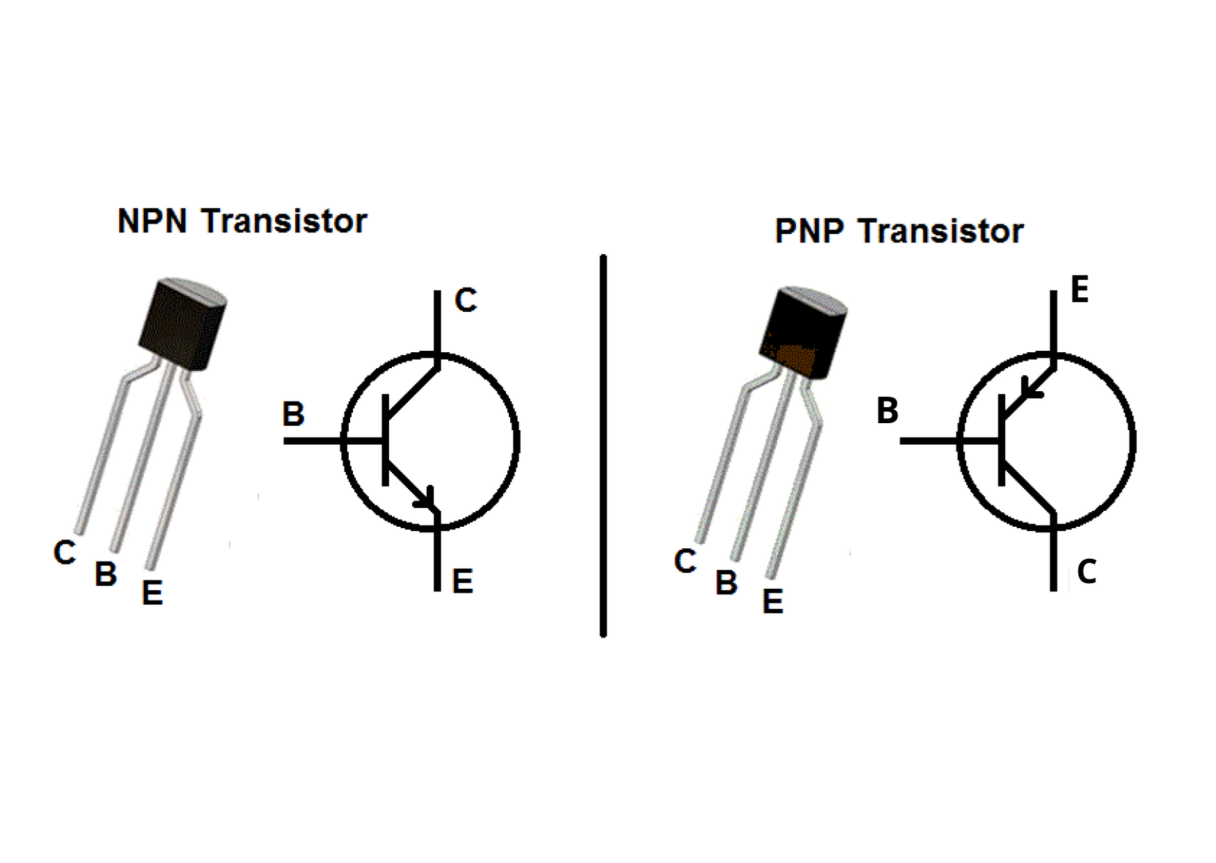
What Is The Difference Between Pnp And Npn Shoptransmitter

How To Wire Discrete Dc Sensors To Plc Part 2 Realpars

Diagram Hall Sensor Wiring Diagram Full Version Hd Quality Wiring Diagram Genuengine Etoiledumarais Fr

Diagram 4 Wire Sensor Diagram Full Version Hd Quality Sensor Diagram Mate Diagram Radd Fr

Bm 7390 120v Photocell Sensor Circuit Schematic 120v Photocell Sensor Circuit Free Diagram

Pin En Electronics

Autonics Counter Timer Counters Ct4s 1p4
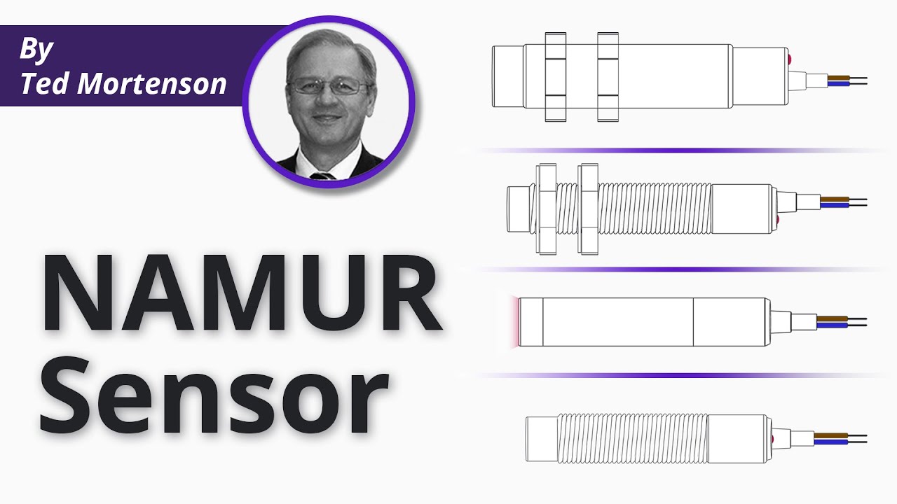
What Is A Namur Sensor Youtube

Cd60 4 Pin Terminals Ac Capacitor 1pcs 500uf 250v Capacitors Ac Capacitor 10 Things