Rs485 Connection Rs 485 Wiring Diagram
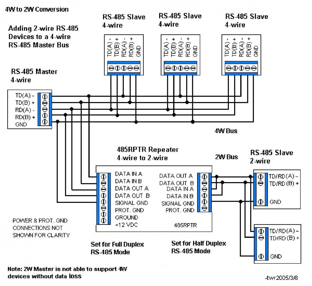
Diagram Mahindra 485 Wiring Diagram Full Version Hd Quality Wiring Diagram Bpgrafic Ahimsa Fund Fr
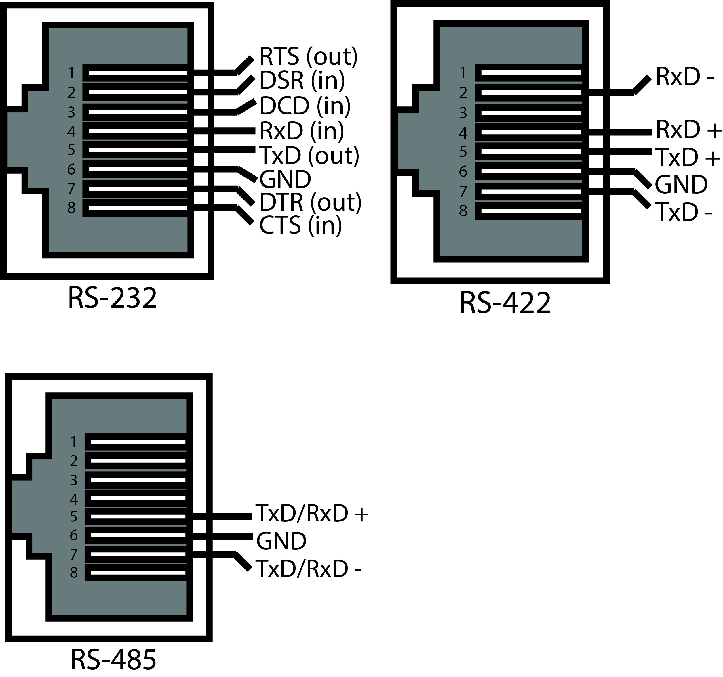
Diagram Rs 485 Pinout Diagram 2wire Full Version Hd Quality Diagram 2wire Structurepvctas Borgocontessa It

Mw 6822 232 To 485 Wiring Diagram Serial Connector Schematic Wiring

Diagram Pelco Rs485 Ptz Wiring Diagram Full Version Hd Quality Wiring Diagram Realityacademy Kinggo Fr

Rs485 To Rs232 Converter Aquaticus
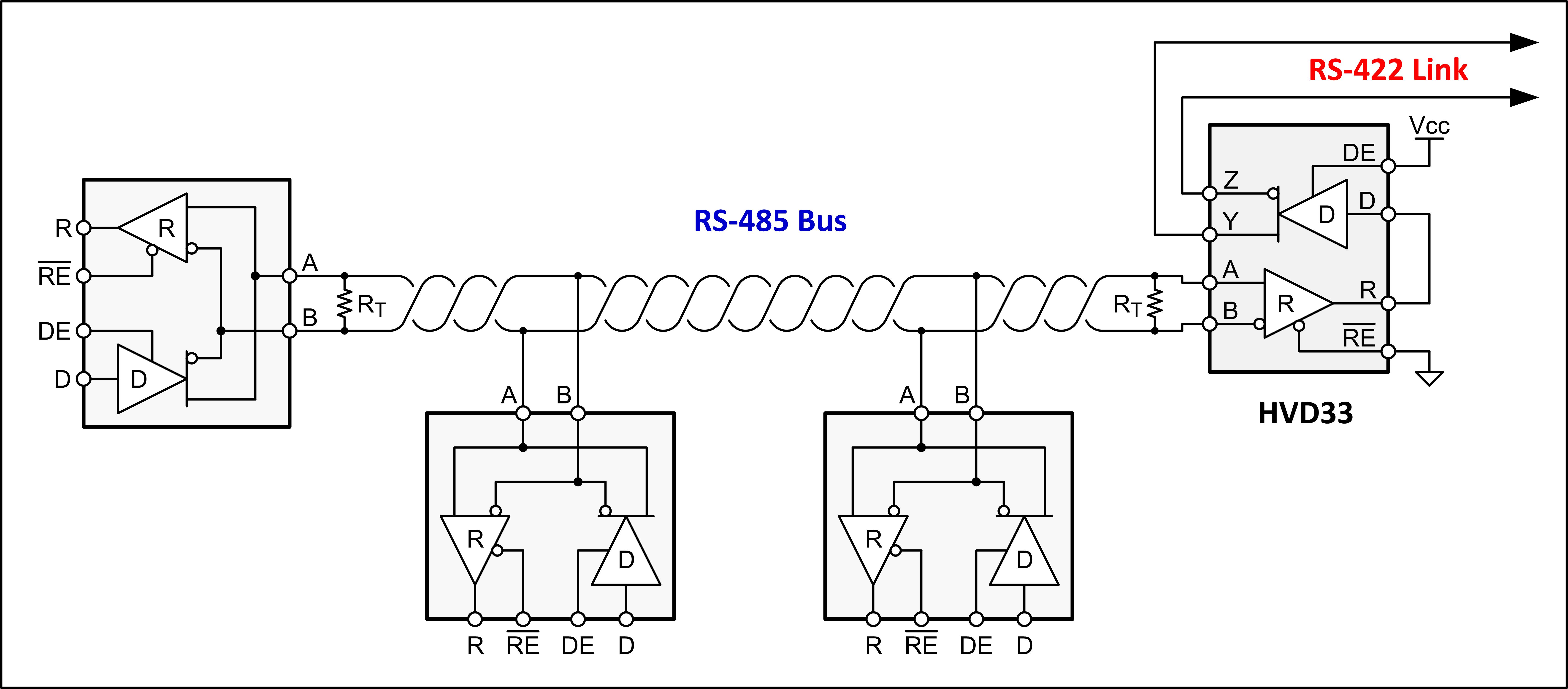
Diagram Mahindra 485 Wiring Diagram Full Version Hd Quality Wiring Diagram Werunwiring Elena Fitness Fr

Figure 4 is a pin diagram for both 25 pin rs485 pinout half duplex and full duplex pinout connectors.
Rs485 connection rs 485 wiring diagram. Figure 3 is an rs485 wiring diagram for rs485 pinout db9 connectors. Go back to modbus rs485 cabling rules 8. These guidelines and sound engineering practices are. Wiring rs 485 networks to wire the connections carefully strip about 1 4 of the conductor insulation insert the bare conductor into the correct terminal orifice and then fasten the screw.
Most of the pins on db 25 connectors are not connected since only nine pins are used for rs 232 rs 422 and rs 485. Variety of rs485 wiring diagram. Rs485 half duplex wiring diagram two wire rs networks operate in half duplex mode on one twisted pair plus a the following diagram shows the daisy chain topology. Refer to set up 2 wire half duplex communication with rs 485 port for the pinouts and more details.
Proper wiring for rs 485. Half duplex 2 wire for 2 wire transmission you will need to short the transmit txd and receive rxd signals together on the rs 485 port. Normally this connection is made at one end of the main cable. Figure 3 applies to most b b rs 485 converters or serial cards that can be set for 2 wire or 4 wire operation and for some 2 wire converters that use the same circuit board for the rs 422 model.
This application note is intended to provide basic guidelines for wiring an rs 485 network. Check the data sheet schematic or block diagram. This connector is not as common as the de 9 connector. Data acquisition articles rs485.
The txd and txd lines carry transmit data while the rxd and rxd contain the receive data. It reveals the parts of the circuit as simplified shapes and the power as well as signal links in between the gadgets. Controlsoft recommends using a slot head screwdriver with a blade 3 32 wide suitable for size 0 or 1 screw. Go back to modbus rs485 cabling rules 7.
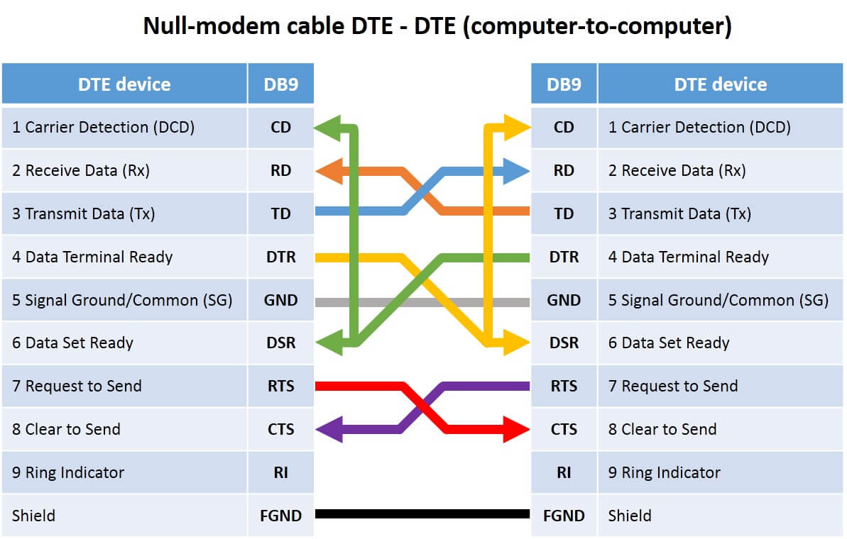
For ni serial hardware connector pinout diagrams refer to the serial quick reference guide. What they are called what information they carry and even the connectors and pin numbers to use. Two switches are set for 2w or to the 2 wire rs 485 mode. But it does give some guidelines.
Understanding rs485 and rs422. This connector can still be used to perform a loopback test with a method similar to the one used for the de 9 connector. Rs422 and rs485 by contrast define only the electrical characteristics of the driver. The cable shield must be earthed only in one point.
The distances these signals are carried is greater due to differential signals. A wiring diagram is a streamlined traditional pictorial representation of an electric circuit. Earth connection of the shield. Those familiar with rs232 will know that the standard defines how rs232 lines should be driven electrically.

Cl 3690 Cable Wiring Diagram Likewise Rs 422 Rj45 Serial Pinout Diagram On Wiring Diagram
The Main Differences Between Rs 232 Rs 422 And Rs 485
Standard Rs 485

99b6a Rs485 To Usb Wiring Diagram Wiring Resources

Ae 1297 Rs485 Wiring Guide Free Download Wiring Diagrams Pictures Wiring Schematic Wiring

Rs 485 Wiring Diagram Electrical Wires Cable Rs 232 Conversion Of Units Angle Electronics Png Pngegg
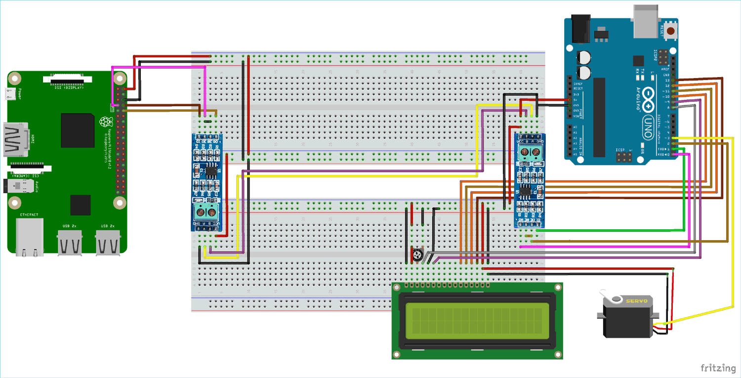
Rs 485 Serial Communication Between Raspberry Pi And Arduino Uno

Diagram Rs485 Connector Wiring Diagram Of An Full Version Hd Quality Of An Kissdiagram Selleriabh It
Pin On Electronics Tutorials

Rs485 Click 5v Breakout Board For Adm485 Transciever Ic

Android Arduino Communication Via Modbus Rs485 Arduino Arduino Projects Diy Arduino Projects

Wiring Diagram For Rs485 Winnebago Wiring Diagrams For Batteries Sources Autso5 Pro Wirings Decorresine It
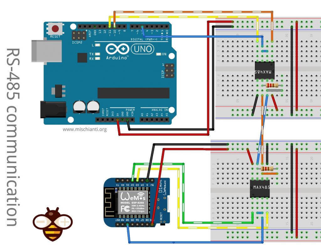
How To Interface Arduino Esp8266 Or Esp32 To Rs 485 Renzo Mischianti
