Sick Photoelectric Sensor Wiring Diagram
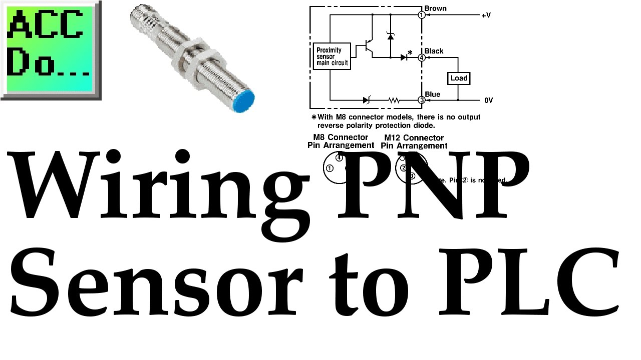
Wiring Pnp Sensor To Plc Youtube

Th 4666 Sick Sensor Wiring Diagram Free Diagram
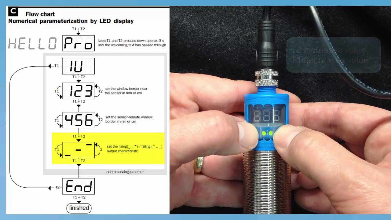
Sick Um30 213113s11 Repogram Youtube

Diagram Sick Sensor Wiring Diagram Full Version Hd Quality Wiring Diagram Thewiringservice Kickboxen Taekwondo De

Sick Essentials 8014219 Manualzz

Tutorial Setup The Glare Sensor From Sick Sick Ag Youtube
Here s a simple way remember how to wire up a 3 wire dc pnp or npn sensor.
Sick photoelectric sensor wiring diagram. Sick s vast range of photoelectric sensors offer precise optics and advanced technology creating market leading solutions with sensor intelligence. A sick wl12 3p2431 photo eye is an excellent example of a basic on off pnp sensor. The sensor has two outputs that may be tied into a programmable logic controller input of the sinking type. 5 with light dark ratio 1 1.
Sick is one of the world s leading producers of sensors and sensor solutions for industrial automation applications. 4 signal transit time with resistive load. It shows the parts of the circuit as streamlined forms and the power as well as signal links between the devices. Additional sensor information can be used to simplify modern production processes.
Variety of photoelectric switch wiring diagram. Symbols that represent the components inside the circuit and lines that represent the connections with shod and non shod. Here is my wiring diagram third photo and instructions. Connect all 3 white wires from house from sensor and from light together.
Dimensions w x h x d 23 8 mm x 43 4 mm x 33 6 mm. A wiring diagram is a simplified traditional photographic representation of an electric circuit. 3 at uv 24 v or ambient temperature 49 c ia max. Now wasn t that easy.
Wiring diagrams are made up of two things. Housing design light emission. Black wire is 120 volts so turn off switch or circuit breaker. A wiring diagram is a form of schematic which uses abstract pictorial symbols to exhibit every one of the interconnections of components inside a system.
Pnp switched positive npn switched negative switched refers to which side of the controlled load relay small indicator plc input is being switched electrically. Either the load is connected to negative and the positive is switched pnp continue reading an easy way to remember pnp and npn sensor. By using the latest siric and led technologies these sensors offer the highest level of operational reliability regardless of any interference factors. 6 a v s connections reverse polarity protected.
7 b inputs and output reverse polarity protected. Safety systems and solutions. Operated in short circuit protected network. The wiring diagram dictates a standard configuration which requires a 24vdc and gnd signals for power.
Sens control safe control solutions. Sick sensor wiring diagram 90 mustang 3phase anggurmasam astrea construction fr bx 3980 free photo eye how to wire a photoelectric into compactlogix allen bradley plc sensors inc training system requirements èpointing device èwindows 95 98 nt èsound card èspeakers or headphones ppt sensing fundamentals back the basics npn vs pnp automation insights yard light base website andvenndiagram. 2 may not exceed or fall below u v tolerances.

Tz 6691 Photoelectric Sensor Schematic Wiring

Proximity Sensor Basics Pnp Capacitive Youtube
Https Cdn Sick Com Media Docs 5 35 135 Product Information G2f En Im0082135 Pdf
Rfu620 Uhf Rfid Read Write Device User Manual Barfu62xen 8015928 20130808 Draft Sick Ag
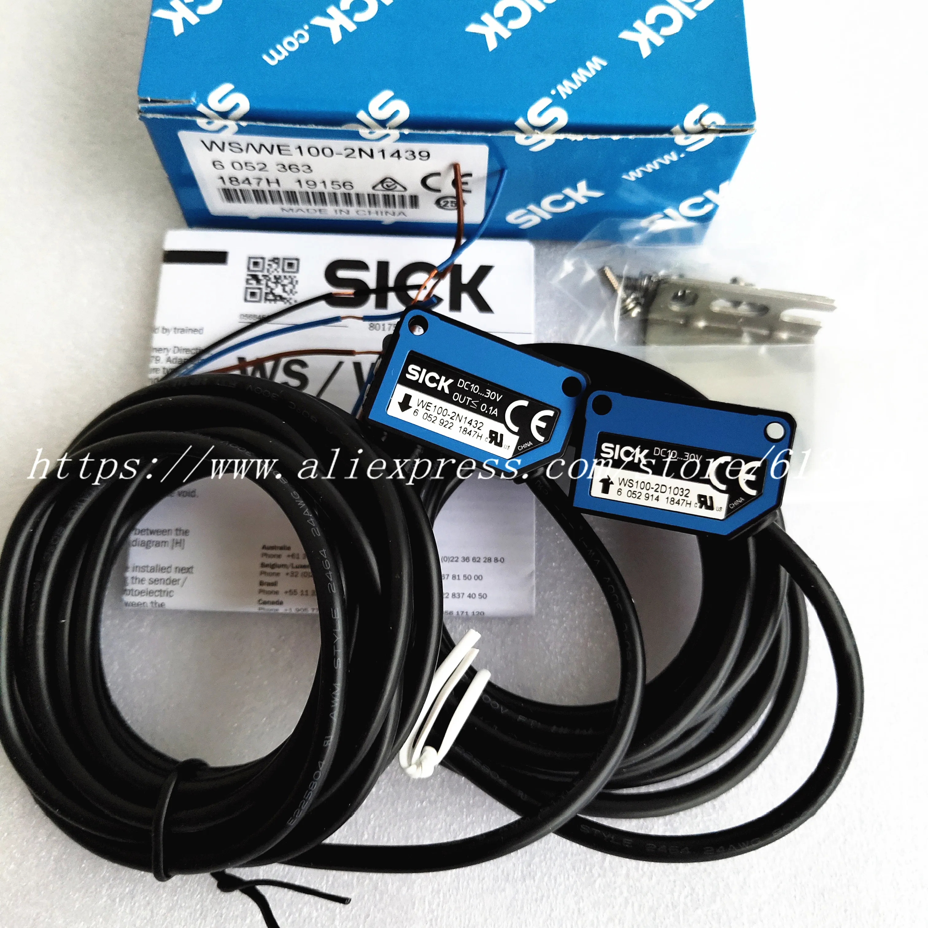
Ws We100 2n1439 100 New Original Sick Photoelectric Switch Sensor We100 2n1432 Ws100 2d1032 Proximity Switch Sensor Switch Sensorinductive Proximity Aliexpress

Proximity Sensor Capacitive Sensing Sick Ag Electric Sensor Proximity Electronics Capacitance Rotary Encoder Png Pngwing

Od Mini New Short Range Distance Sensor Displacement For Micrometer Precise Measurement Sick

Light Switch Wiring Diagram Australia Hpm Photoelectric Sensor To Outdoor Ceiling For Outside Mot Motion Sensor Lights Light Switch Wiring Photoelectric Sensor

Safety Relay Sick And Emergency Stop Button In 2020 Relay Emergency Current Transformer
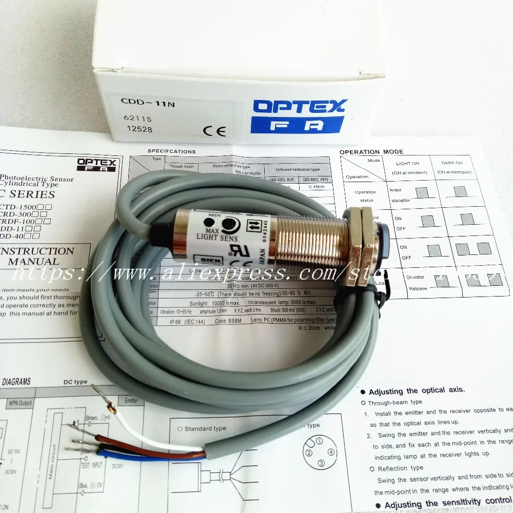
2pcs Cdd 11n Cdd 11p Sick Optex No Nc M18 New Photoelectric Switch Sensor High Quality Switch Sensor Sensor Sensorsick Photoelectric Sensors Aliexpress

How To Install Omron E3jm Photo Eyes On Powermaster Operators Youtube
Https Cdn Sick Com Media Pdf 8 38 638 Datasheet Wtb2s 2p1151 1066110 En Pdf
Https Www Sick Com Media Pdf 5 95 895 Datasheet Wse9m4 3p2230 1051912 En Pdf
