Tach Vdo Tachometer Wiring Diagram

Elegant Temperature Gauge Wiring Diagram In 2020 Tachometer Boat Wiring Diagram

Pin On Lighting

Yamaha New Oem Multi Function Gauge Tachometer 6y5 8350t D0 00 Want Additional Info Click On The Image This Tachometer Things To Sell Digital Alarm Clock
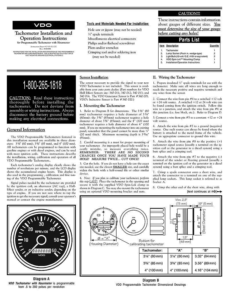
Vdo Programmable Tach With Hourmeter

Pin On Computers Tablets Networking
Vdo Tachometer Installation Manual

8 pin connection f1 fuse 5a quick response c1 8 pin mqs connector you must comply with the wiring diagram.
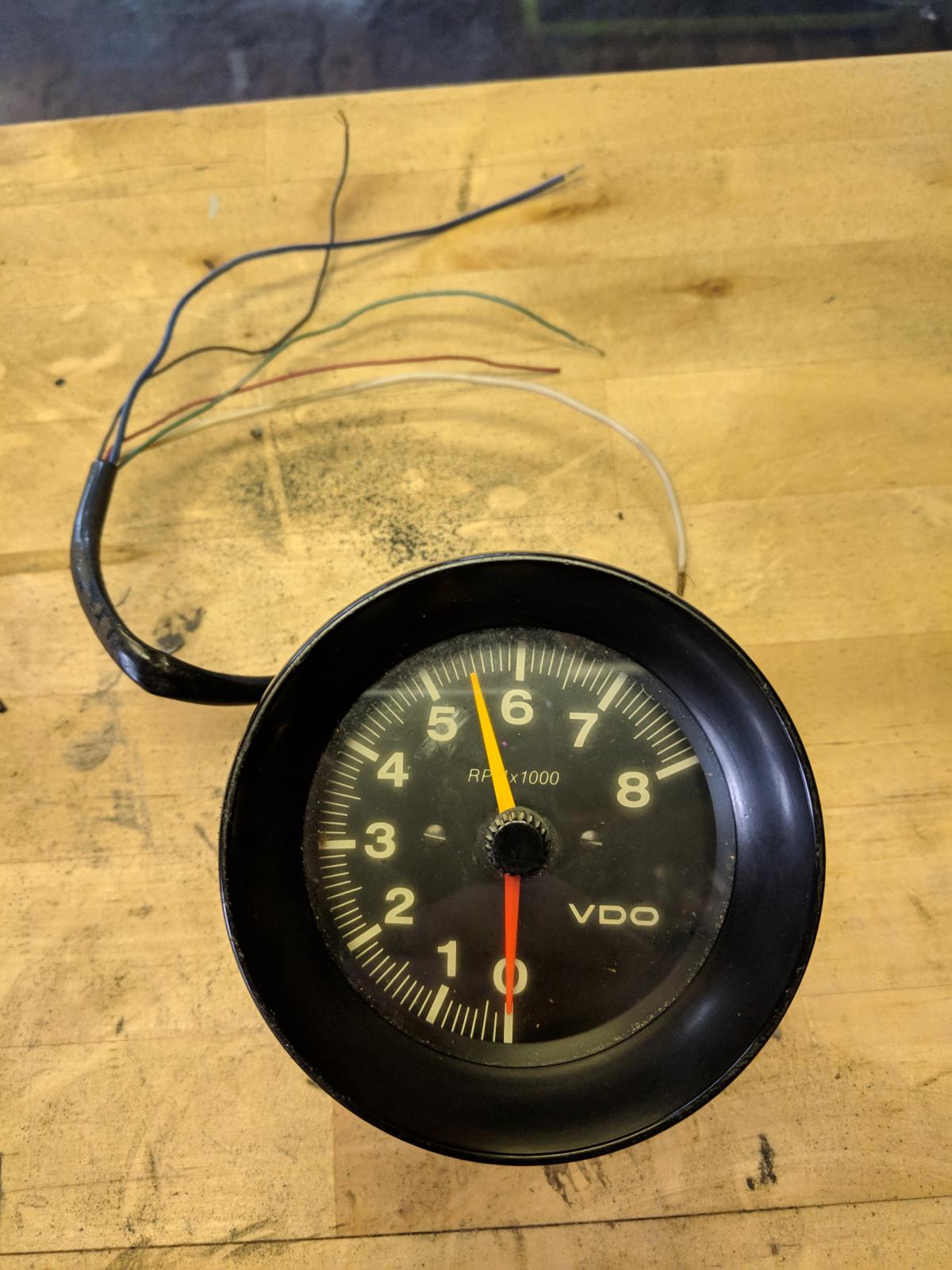
Tach vdo tachometer wiring diagram. Wiring connect the tachometer wires as shown. White red black green grommet. Always disconnect battery ground before making any electrical connections. Wiring diagram rpm vdo gauges.
A the battery constant power after the fuse box or user supplied in line fuse 5 amp fast blow. Connect the wire from. If in doubt please contact your dealer or vdo. When the vdo tachometer reading.
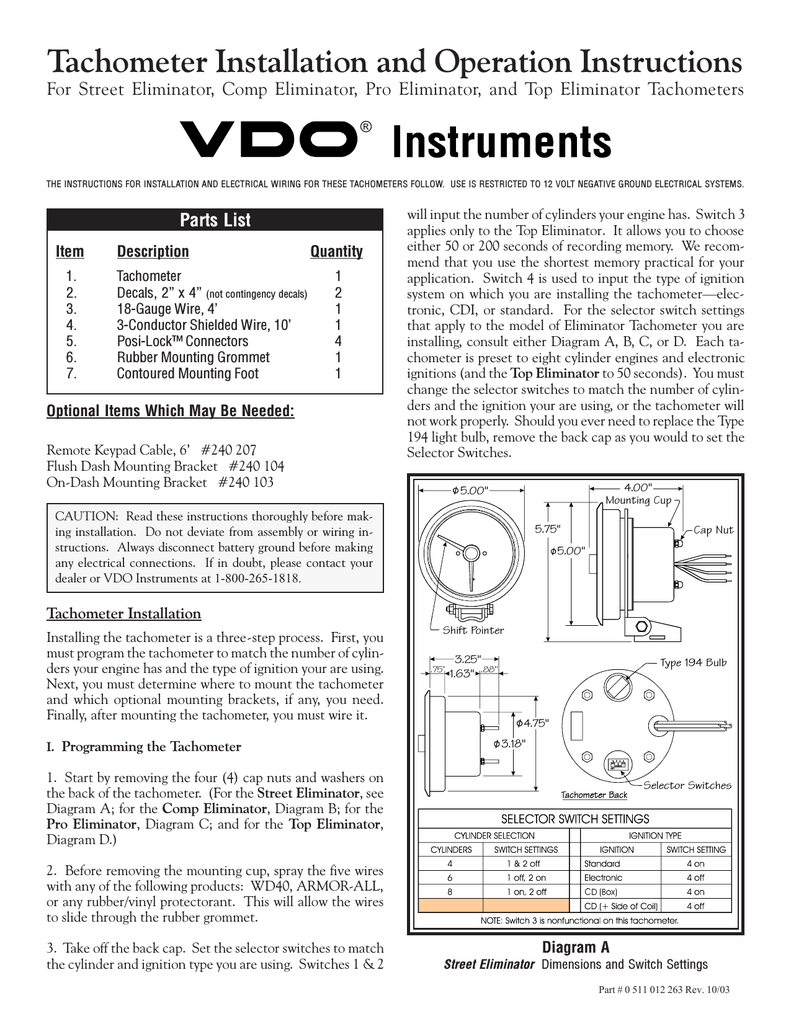
12v battery coil ignition coil tach base can be mounted in either direction for convenient mounting. Wiring the tachometer turn off the ignition and disconnect the negative terminal from the battery post if you haven t already done so. Read these instructions thoroughly before making installation. Wire the tachometer to the vehicle as shown in either diagram c or diagram d.
Mount the gauge and secure with the vdo spin lok clamp. Tachometer without display 13 gb 14 connector set 8 pin a2c59510850 30 terminal 30 steady state plus 12 v 15 terminal 15 connected ignition plus 58 terminal 58 lighting 31 terminal 31 ground designations in the wiring diagram. Vdo does not recommend mounting your xtreme 3. Boat gauge wiring diagram for tachometer.
Vdo tach pin1 3 4 labeling. Vdo vdo cockpit 7 000 rpm 3 1 8 in tachometer 12v. Vdo 8 in vision black 4 000 rpm electric. You may also mount the tachometer using an optional vdo mounting bracket and nuts.
Route wires from the instrument to. Refer to your vehicle s owner service manual or the. Diagram f fine adjustment of the vdo tachometer when used with an alternator compare the vdo tachometer reading with that of a reference tachometer. Make sure all wires are long enough to reach the necessary positive and negative terminals and any wires from the sensor.
Mounting the tachometer 1. Vdo spin lok clamp or mounting bracket 1 5. Conventional ignition system. For chrysler blue gold and silver boxes ford standard electronic ignitions and most other oem standard cd and electronic ignitions.
See page 4 for mounting options and instructions wiring the gauge illustration a. The wiring diagram shown is a typical installation. Installation instructions 1 caution. Adjust the potentiometer on the back of the tach.
Tach with display 85mm 4 pages measuring instruments vdo contisys obd quick reference manual 59 pages summary of contents for vdo tachometer. See page 2 setting up the tachometer. Do not deviate from assembly or wiring instructions. Shown in diagram c.

Pin On Lighting Electrical

85mm Black Stainless Steel Gps Speedometer 0 160mph For Car Truck Motorcycle Motorcycle Accessories Parts From Automobiles Motorcycles On Banggood Com In 2020 Cars Trucks Black Stainless Steel Trucks

Faria Beede Instruments Kt9797 Inboard Dress White 6 Gauge Boxed Set Find Out More About The Great Product At The Image Link T Set Dress Tachometer Gauges

Pin On Products

Vdo Vdo 3 3 8 In Cockpit Royale 7 000 Rpm Programmable Tachometer 12v With 250 In Spade Connection 333 708 333 708
Sponsored Ebay 52mm White Blue Maxtow Double Vision 1500f Pyrometer Egt Gauge Mt Wbdv08 1500 Fuel Pressure Gauge Air Pressure Gauge Double Vision

Pin On Www Diagauto Lt
Thesamba Com Beetle Late Model Super 1968 Up View Topic Vdo Tachometer Wiring Unable To Find Diagram

Diagram Mopar Electronic Ignition Wiring Diagram Tach Connection Full Version Hd Quality Tach Connection Priceengineauto Amandine Brevelay Fr

Super Loud 148db Marco Extreme Blast Premium Air Horn Car Truck Suv Black Matte To View Further For This Item Visit The Image Link Cars Trucks Trucks Car

Key Fob Keyless Entry Remote Fits Honda Odyssey 2005 2006 2007 2008 2009 2010 Oucg8d 399h A 6 Btn Set Of 2 More Info Cou Automotive Honda Odyssey Keyless

Kameari 1 3 4 Exhaust Header Fujitsubo Stainless Steel Exhaust Motocikl
