Vav Thermostat Wiring Diagram

Pin On Wire
Thermostat Wiring Diagrams 10 Most Common Youtube

New Bryant Gas Furnace Wiring Diagram Diagram Diagramsample Diagramtemplate Wiringdi Electrical Circuit Diagram Thermostat Wiring Electrical Wiring Diagram

Luxury Ford Wiring Diagram For Trailer Plug Diagrams Digramssample Diagramimages Wiringdiagramsample Wiringdiagram Check More A Duct Work Diagram The Unit

Olympian Generator Wiring Diagram 4001e Collection In 2020 Electrical Circuit Diagram Transfer Switch Electrical Wiring Diagram

Unique Simple Electrical Circuit Diagram Diagram Wiringdiagram Diagramming Diagramm Electrical Circuit Diagram Basic Electrical Wiring Electrical Diagram

Wireless vav communication may 2001 vav svx01b en american standard inc.
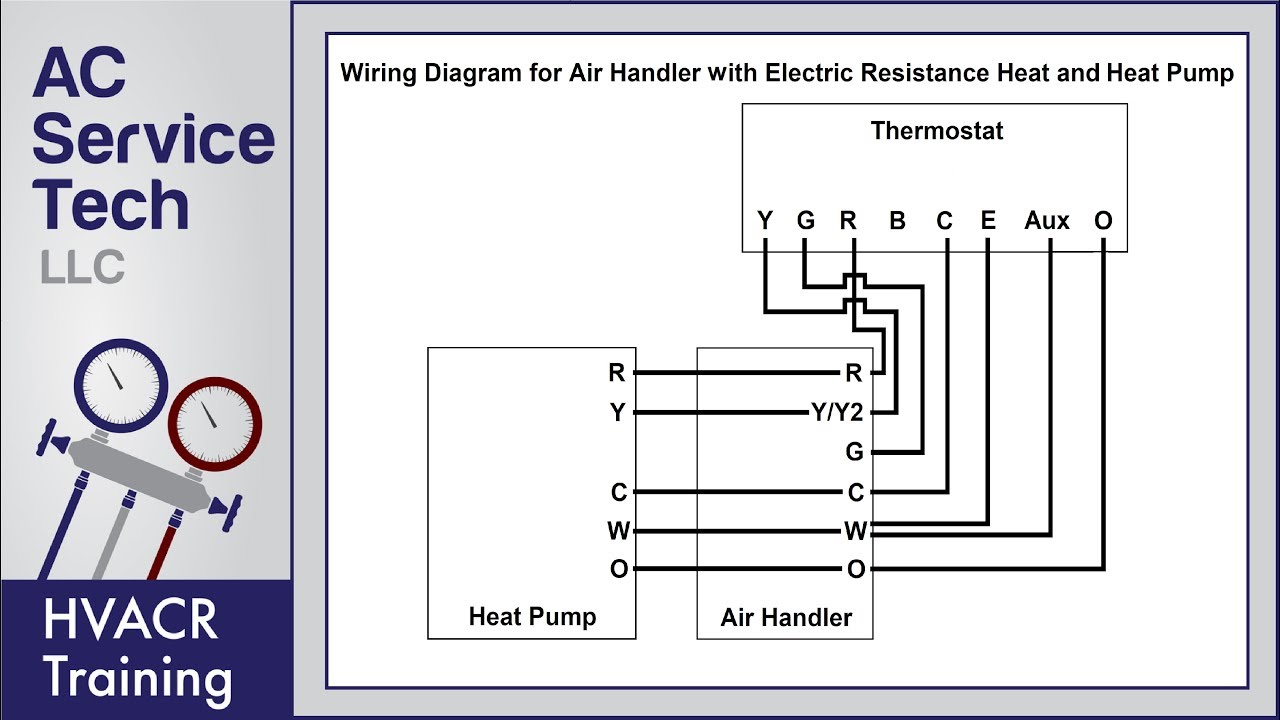
Vav thermostat wiring diagram. Refer to the following table for the description. Resistance resistance f ohms k ohms 55 792 17 0 56 772 16 5. Supply connections must be made using wires rated for 75oc minimum. Thermostat wiring diagrams for heat pumps heat pump thermostat wire diagrams.
When unit is in full by pass position adjust the by pass. Reinstall the thermostat onto its base and secure with the cap tive screw. Thermostat thumbwheel sensor temp. 2 vav controller variable air volume vav controller wiring details page 25 power source and loads 26 grounding and isolation 27 i o and communication terminals 29 power zone bus and n2 connections 36 analog inputs 36 binary inputs 38 binary outputs 38 analog outputs 38 zone bus 39 wiring to rly50 002 relays 39.
Color of wire and termination. Each vav unit and accessory is shipped with an. It is a red wire and comes from the transformer usually located in the air handler for split systems but you may find the transformer in the condensing unit. Wiring diagram figure 1 shows a typical wiring diagram.
Thermostat for full heat full by pass position. Heat pumps are different than air conditioners because a heat pump uses the process of refrigeration to heat and cool while an air conditioner uses the process of refrigeration to only cool the central air conditioner will usually be paired with a gas furnace an electric furnace or some other method of heating. 2 2 terminal designations the designations of the terminals vary according to the particular model of thermostat. See section 2 2 for terminal designations and section 3 for typical wiring diagrams.

Dsc Wiring Diagram For Homestereoinstallation Home Security Systems Wireless Home Security Systems Home Security
Unique Wiring Diagram Electric Gates Diagram Diagramsample Diagramtemplate Wiringdiagram Diagra Electrical Wiring Diagram Electric Gates Motorcycle Wiring

New Doorbell Wiring Diagram Uk Diagram Doorbell Wire

17 Clifford Car Alarm Wiring Diagram Car Alarm Diagram Electrical Circuit Diagram

Led Light Bar Relay Wire Up At Wiring Diagram For 12v Led Lights In Motorcycle Wiring Light Switch Wiring 12v Led Lights

Unique Wiring Diagram For American Standard Gas Furnace Diagram Diagramsample Diagramtemplate Heat Pump Refrigeration And Air Conditioning Thermostat Wiring

Wiring Diagram For 220 Volt Baseboard Heater Http Bookingritzcarlton Info Wiring Diagram For 2 Baseboard Heater Thermostat Wiring Electric Baseboard Heaters

220v 30a Wiring Diagram Help Page 2 Home Brew Forums Home Brewery Home Brewing Brewery

Pin On Kc

New Audi A4 Air Conditioning Wiring Diagram Diagram Diagramtemplate Diagramsam Refrigeration And Air Conditioning Electrical Circuit Diagram Circuit Diagram

Disposal Wiring Diagram Home Electrical Wiring Garbage Disposal Garbage Disposal Installation

Wiring Diagram Mtd Lawn Tractor Wiring Diagram And By Lawn Mower Ignition Switch Wiring Diagram And Gif Fair Mtd Yard Machine Diagram Design Diagram

Mlm Fan Coil Unit Controller Wiring Diagram Rickardair
